Chart Editor
A chart is a single tabular or graphical representation of results in the form of a Diagram, a table, or HTML output. Charts are created based on preconfigured data sets (see Dataset Editor).
The chart library used in the Analysis module is AmCharts. See the official documentation at
The following chart types can be generated:
-
Charts based on data objects with numeric attributes
-
Charts based on data objects with different attributes
-
Charts based on lists (arrays)
User Interface
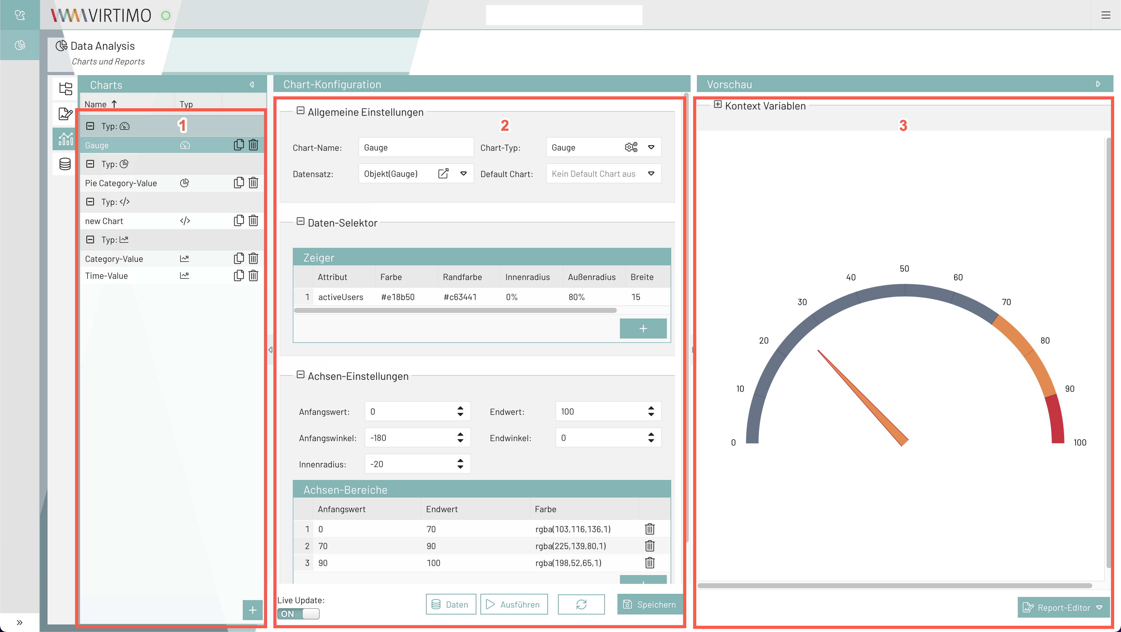
-
List of individual charts
-
Configuring charts
-
Preview of a chart
In the first section, the Charts Overview, you can add, edit, duplicate, and delete new charts (see Buttons and Icons).
In the second section, a chart type is selected and graphically customized based on a suitable dataset.
The chart settings can be directly visualized and checked in the third section, the preview.
Adjusting Panels
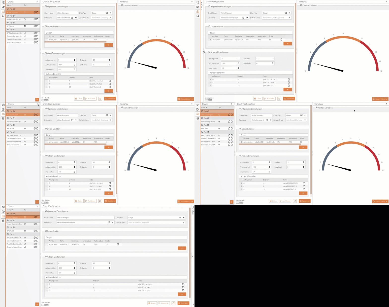
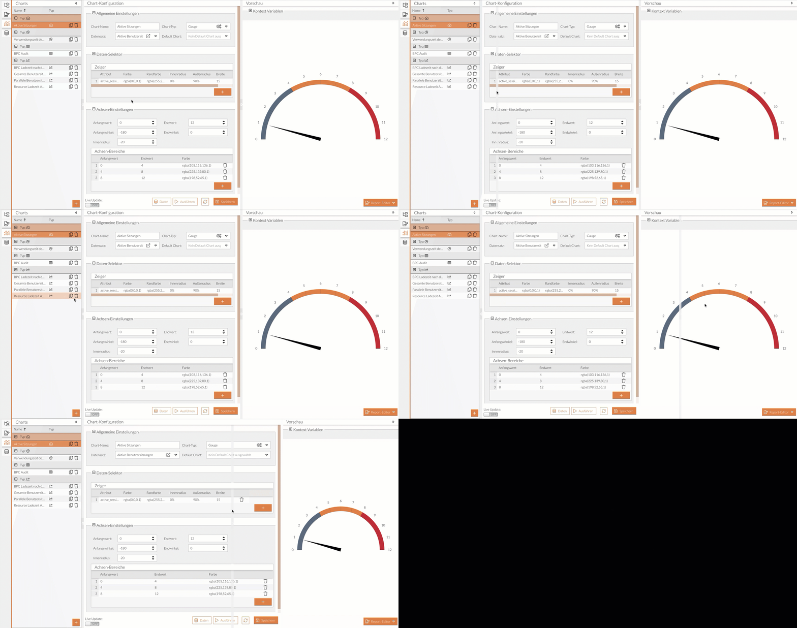
The width of individual panels can be adjusted or they can be completely collapsed, for example, to reveal hidden information.
Expand or collapse sections:
Adjust the width of sections:
Live Update
- What is the "Live Update" feature used for?
-
Enabling Live Update ensures that changes to the chart are immediately visible in the preview area.
- When should Live Update be disabled?
-
If you need to display comprehensive charts with many data points, rendering and visualizing the charts requires more resources. Depending on your individual resources, this can affect the application’s performance.
Therefore, if you notice or expect limitations during configuration or slow rendering in the preview area, disable Live Update.
Buttons and Icons
| Button/Icon | Description |
|---|---|
Add |
Creates a new element. |
Copies the selected chart, including all configurations, and adds the copy to the end of the list or the end of the group. |
|
Removes the selected element. |
|
Opens the group and displays all entries assigned to this chart type. |
|
Closes the group and minimizes all entries assigned to this chart type. |
|
Opens a window where you can configure advanced settings for the chart’s appearance. |
|
Opens the selected dataset in the dataset editor. |
|
Updates the chart view in the preview area (used as the default if Live Update is disabled) |
|
Run |
Generates a chart based on the entered data and Parameters. |
Save |
Saves entries and settings. |
Report Editor |
Opens an “Add New” selection button. Clicking this adds the current chart to the list of reports. |
Create a New Chart
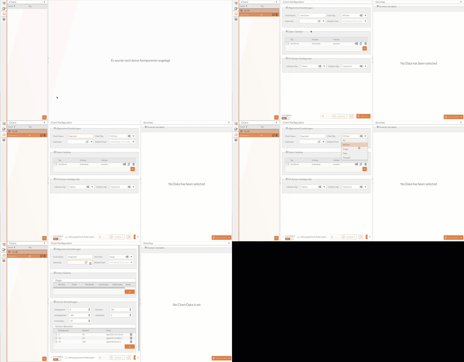
When adding a new chart, the XY chart is the default chart type.
|
If Live Update is turned off, you must click the Refresh button to see changes in the Diagram. |
-
In the Analysis module, select the Chart Editor.
-
Add a new chart.
-
Enter a name.
-
Select a chart type.
-
Select a data set.
-
Adjust the data selector and, if necessary, the configurator depending on the chart type.
A chart has been created and can now be further configured.
General Settings
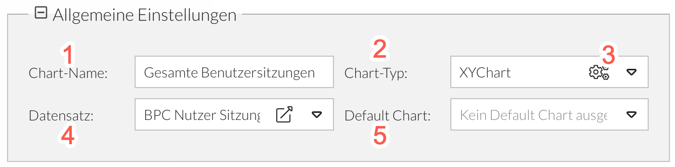
The general settings are the same for all chart types:
-
Chart name, which is also visible in the Report Editor and in the widget
-
Selection of a dataset created in the Dataset Editor, which the chart can access
-
Selection of the chart type
-
Preconfiguration depending on the selected chart type
Advanced Settings
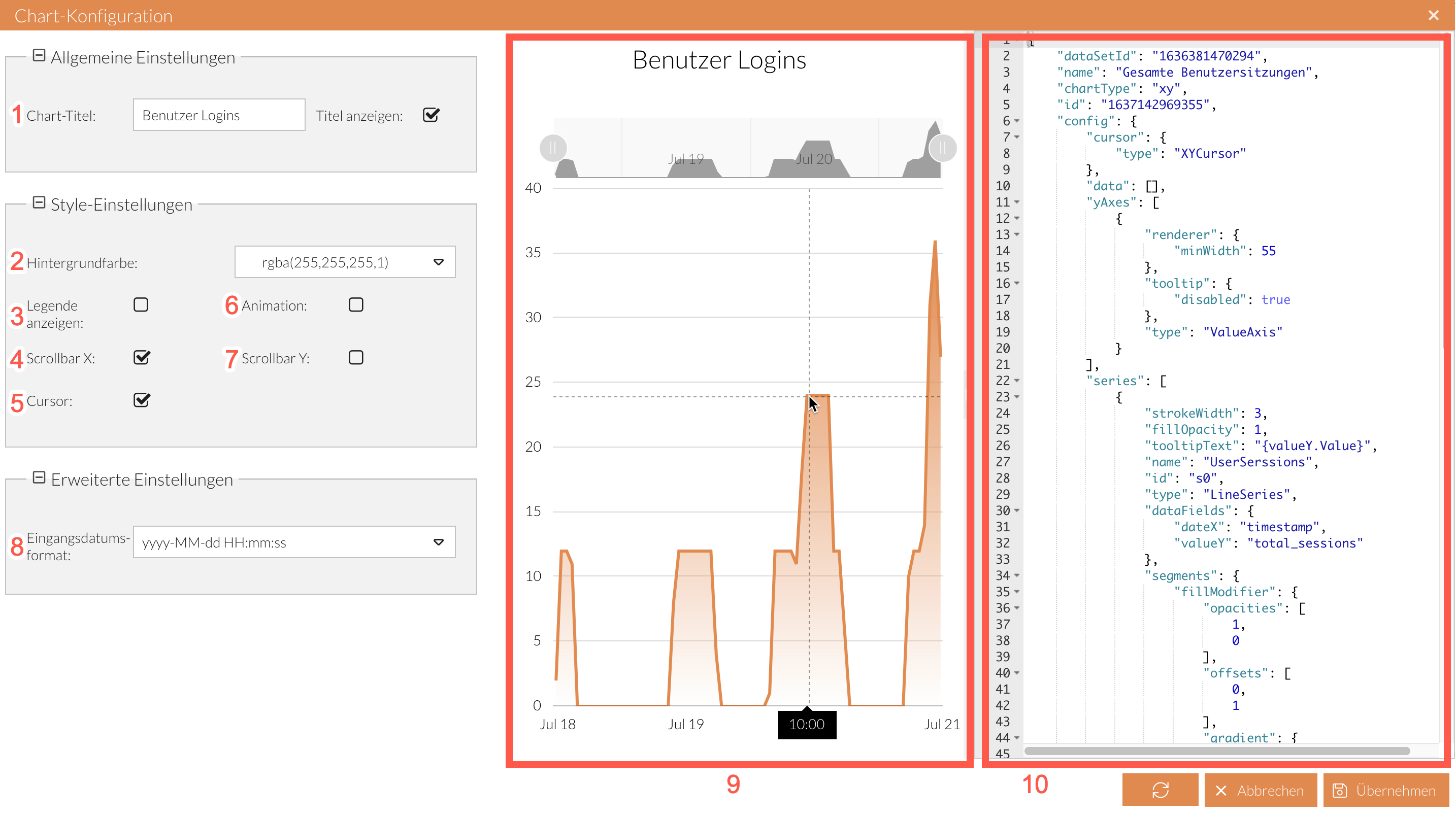
The advanced settings are the same for all chart types, but some of the options are only suitable for certain charts.
|
Before you can configure advanced settings, you should at least add values in the data selector. Otherwise, a chart preview will not be available. |
-
Title displayed in the chart (if this option is enabled)
-
Chart background color
-
Displays a legend in the chart
-
Overview panel above the chart where the value range of the X-axis can be restricted
-
Displays a cursor as well as vertical and horizontal lines in the chart to make it easier to read the current value
-
Animation
-
Overview display next to the chart where the value range of the Y-axis can be restricted
-
Date format for data to be displayed on a timeline
-
Preview of the chart
-
JSON structure of the chart configuration
The attribute configuration corresponds to the AmCharts 4 configuration; see the AmCharts 4 documentation.
|
The attribute ID of a chart (see the JSON structure in the advanced settings ) must be unique across all components. |
Tacho Diagrams (Gauge Diagrams)
The gauge diagram consists of a circle and a pointer that points to a value on the circle. This diagram expects a dataset containing exactly one data object with a numberattribute. This is the only way the pointer can point to a specific value.
Data Selector - Customize Pointer
The Diagram’s pointer is configured in the “Data Selector” section. You can configure the pointer’s appearance and specify which value should serve as the basis for the pointer.
{
  "value1":  50,
  "value2" : 40
}-
Click the Add button.
A new entry is added. -
Click in the attribute field.
-
If there are multiple attributes in the dataset, select an attribute from the drop-down list.
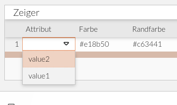
In principle, multiple attributes—and thus multiple pointers—are also possible.
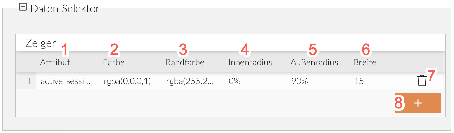
-
Attribute selected from the dataset.
Click in the field and select the desired value from the drop-down list.
.Fill color of the pointer.
Double-click the field and select a color from the color picker.
The inner radius determines the distance from the pointer base to the center of the circle.
The outer radius determines the distance from the pointer tip to the center of the circle.
of the pointer base in pixels.
Removes the selected pointer.
Adds a new pointer.
Axis Settings - Customize Circle
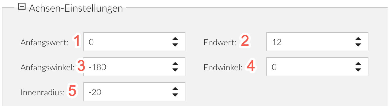
The axis settings allow you to customize the appearance of the (half) circle.
-
The starting value of the value range.
No unit is specified. -
The ending value of the value range.
No unit is specified.
The intervals between the starting and ending values are automatically adjusted to the selected value range. -
The start angle determines the position of the start value on a circle.
-
The end angle determines the position of the end value on a circle.
-
The inner radius controls the width of the colored axis ranges.
Styling
The following colors can be customized:
-
Pointer color—see Fill Color and Border Color
-
Axis range color Axis range
HTML Diagrams (Template Charts)
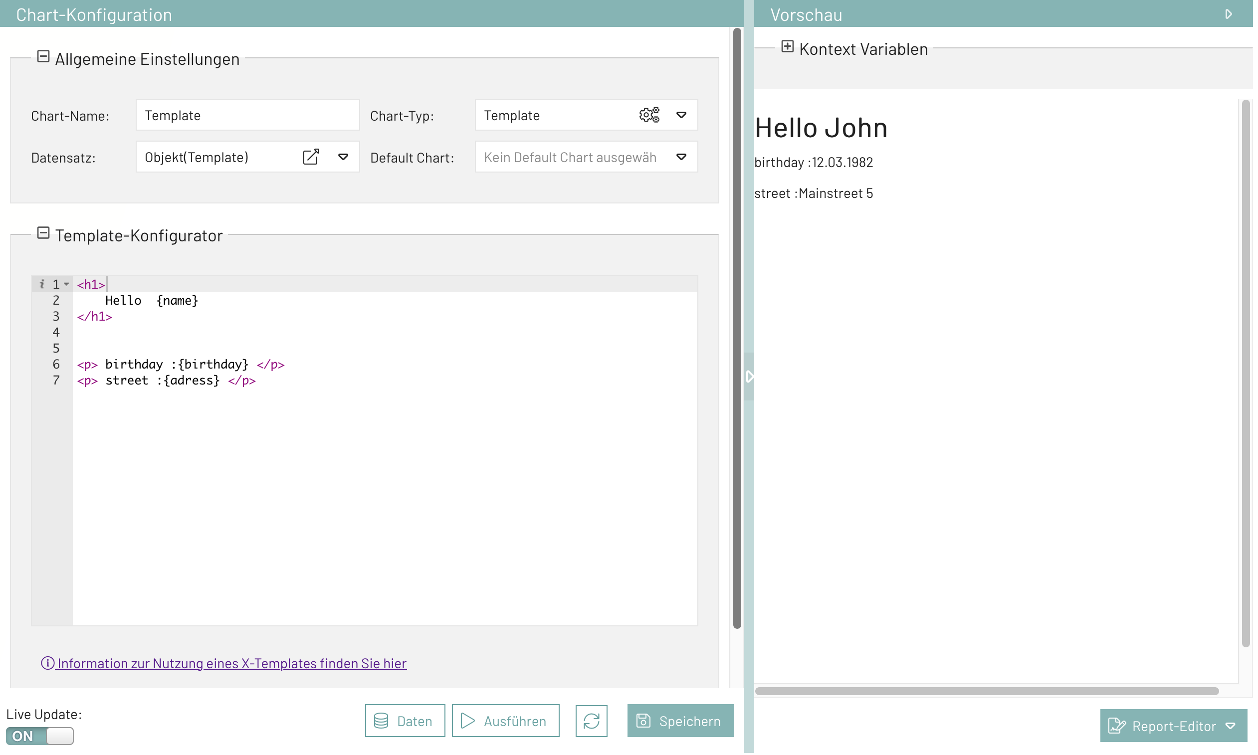
The template diagram offers a great deal of design flexibility. Here you can customize and display data by embedding it in HTML content. This allows you to incorporate values from the dataset into text, for example.
{
  "name":  "John",
  "birthday" : "12.03.1982",
  "address" : "Mainstreet 5"
}
Template Configurator
The HTML content is stored in the Template Configurator. Data is accessed via attributes enclosed in curly braces. The content is interpreted as `Ext.XTemplate `, whereby the data is already automatically bound to the data object from the selected data record.
<h1>Hello {name}</h1>All constructs such as iterations and if-else conditions from ` Ext.XTemplate ` are available.
Pie Charts
Pie charts are suitable for displaying proportions and (e.g., percentage) distributions.
[
    {
        "module": "Analysis",
        "usage_time": 5898712
    },
    {
        "module": "Core",
        "usage_time": 8011348
    },
    {
        "module": "Dashboard",
        "usage_time": 1909192
    }
]
Data Selector - Customize Pie Slices
After selecting a dataset previously configured in the Data Set Editor, you can choose attributes from the data in the Data Selector.
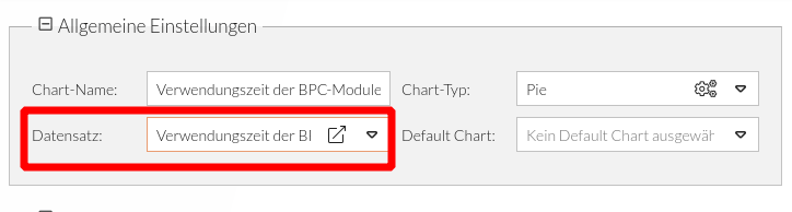
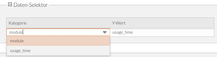
It makes sense to select the attribute of the alphanumeric value in the dataset as the "Category" (in the example, "module") and the attribute of the numeric value as the "Y-Value" (in the example, "usage_time")
Pie Configurator - Design chart
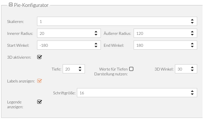
The Pie Configurator offers the following settings:
| Label | Description | Example value |
|---|---|---|
Scale |
Numeric value to adjust the overall size of the pie chart |
1.5 |
Inner radius |
Numeric value to adjust the size of the inner radius |
20 |
Outer radius |
Numeric value to adjust the size of the outer radius |
120 |
Start angle |
Numeric value to set the angle at which the pie Diagram begins |
-180 |
End Angle |
Numeric value for the angle at which the pie Diagram ends |
180 |
Enable 3D |
Display as a 3-dimensional pie Diagram |
- |
Depth |
Depth of the 3-dimensional pie Diagram (only for 3D) |
45 |
Use values for depth display. |
Y-value-dependent depth of the 3-dimensional pie chart in (only for 3D) |
|
3D angle |
Viewing angle of the pie chart (only for 3D) |
|
Show Labels |
Display Labels (category and percentage) on the chart |
|
Font size |
Numeric value for the font size of the Labels (for Labels only) |
|
Show legend |
Show legend (color, category, and percentage) at the bottom of the chart |
Styling
Two options are presented for setting the colors of individual pie slices.
The colors are defined in the chart configuration under series → colors → list.
{
    "dataSetId": "1765462730967",
    "name": "Verwendungszeit der BPC-Module",
    "chartType": "pie",
    "id": "1765462804881",
    "enabled3D": true,
    "config": {
        "depth": 20,
        "data": [],
        "series": [
            {
                "type": "PieSeries3D",
                "category": "module",
                "value": "usage_time",
                "dataFields": {
                    "category": "module",
                    "value": "usage_time"
                },
                "colors": {
                    "list": [
                        "#cbbc6b",
                        "red",
                        "rgb(128,100,100)",
                        "rgba(100,200,100,0.7)"
                    ]
                }
            }
        ],
        "background": {
            "fill": "rgba(255,255,255,0)"
        },
        "angle": 30,
        "scale": 1,
        "titles": "",
        "radius": 120,
        "innerRadius": 20
    }
}
2. Colors are defined in the data:
The input data contains an attribute that corresponds to the color value; in this case, ` dataColor`:
[
    {
        "module": "Dashboard_default_dashboard\nundefined",
        "usage_time": 41044.20053708553,
        "dataColor": "green"
    },
    {
        "module": "Core_core_module\nundefined",
        "usage_time": 6314547,
        "dataColor":  "rgb(128,100,100)"
    },
    {
        "module": "Monitor_process-starter-forms\nundefined",
        "usage_time": 3978150.25,
        "dataColor": "#cbbc6b"
    }
]
To enable the assignment of color values to the data series, the attribute ` dataColor ` is referenced in the chart configuration, as shown in the following example.
The reference is made by setting the value of series → slices → template → propertyFields → fill to the attribute in the input data—in this case, ` dataColor `.
{
    "dataSetId": "1765462730967",
    "name": "Verwendungszeit der BPC-Module",
    "chartType": "pie",
    "id": "1765462804881",
    "enabled3D": true,
    "config": {
        "depth": 20,
        "data": [],
        "series": [
            {
                "type": "PieSeries3D",
                "category": "module",
                "value": "usage_time",
                "dataFields": {
                    "category": "module",
                    "value": "usage_time"
                },
                "slices": {
                    "template":{
                        "propertyFields":  {
                            "fill": "dataColor"
                        }
                    }
                }
            }
        ],
        "background": {
            "fill": "rgba(255,255,255,0)"
        },
        "angle": 30,
        "scale": 1,
        "titles": "",
        "radius": 120,
        "innerRadius": 20
    }
}
As shown in the examples, color values can be specified as hex codes, named colors (strings), or in RGB or RGBA format.
Line and Bar Charts (XY Charts)
XY charts include all Diagram types that can be displayed on two axes. These include line Diagrams, 2D bar Diagrams, and 3D bar Diagrams.
Data Selector - Add Data Series
[
    {
        "timestamp": "2022-06-20T04:00:00.000Z",
        "total_sessions": 2
    },
    {
        "timestamp": "2022-06-20T05:00:00.000Z",
        "total_sessions": 6
    },
    {
        "timestamp": "2022-06-20T06:00:00.000Z",
        "total_sessions": 12
    }

]
-
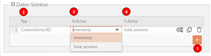
Clicking the Add button adds a data series.
-
Type Selection
-
LineSeries: Display data series as a line or area
-
ColumnSeries: Display data series as bars
-
ColumnSeries3D: Display data series as three-dimensional bars
-
ConeSeries: Display a data series as three-dimensional cones
-
-
Select the data attribute on the X-axis
-
Select the data attribute on the Y-axis
In the XY-Axis Configurator, the X-axis type is set to "Date."
The date value in the sample dataset is contained in the "timestamp" attribute.
In the XY-Axis Configurator, the Y-axis type is set to "Numeric."
The numeric value in the sample dataset is found under the "total_sessions" attribute.
This makes the X-axis of the chart a time axis and the Y-axis a value axis.
Configuring Axes Based on Data Type
It is recommended to first set the axis type in the XY Axis Configurator according to the data type.

The following options are available for both axes:
-
Date (time-based values)
-
Numeric (numeric values)
-
Text
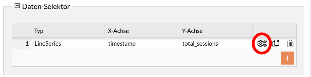
Additionally, specific configurations may be required for individual data series, particularly if they are displayed incorrectly. These configurations should be set individually for each data series. To adjust the settings for a data series, click the gear icon in the data selector.
Numeric Values
If an axis displays numeric values, such as revenue, the valueX or valueY attribute must be set to the corresponding data field.
{ "year": 2023, "revenue": 50000 }In the chart series configuration, valueX should point to "year" and valueY to "revenue" if the years are to be displayed on the x-axis and revenue on the y-axis:
{

    "type": "LineSeries",
    "dataFields": {
        "valueX": "year",
        "valueY": "revenue"
    }

}
Date values
If an axis uses a time-based format such as days, months, or years, the attribute dateX or dateY is required.
{ "date": "2024-03-01", "temperature": 15 }In this case, dateX would need to be set to "date" and valueY to "temperature" if the date is to be displayed on the X-axis and the temperature on the Y-axis.
Categories (Text Values)
If an axis contains text values such as product names, categories, or locations, categoryX or categoryY must be used.
{ "product": "Smartphone", "sales": 1200 }In this case, categoryX would need to be set to "product" and valueY to "sales" if the product is to be plotted on the X-axis and sales on the Y-axis.
{

    "type": "LineSeries",
    "dataFields": {
        "categoryX": "product",
        "valueY": "sales"
    }

}
Default Configuration for New Data Series
For newly added data series, the default configuration is set as follows:
{
    "type": "ColumnSeries",
    "dataFields": {
        "valueX": "timestamp",
        "dateY": "value"
    }
}
If these settings are not appropriate, they should be adjusted manually to ensure the data is displayed correctly.
Styling
The colors in the XY charts are applied similarly to those in the pie chart.
Applies to both line charts and bar charts. Each series is assigned a color in the order specified in the color list.
Applies exclusively to bar charts. Each bar is assigned the color value from the input data.
The assignment of color values differs slightly from that in the pie chart.
The reference, value series → columns → template → propertyFields → fill, is set to the attribute in the input data, in this case ` dataColor `.
{
    "series": [
          {
                "columns": {
                    "template": {
                        "propertyFields": {
                            "fill": "dataColor"
                        }
                    }
                }

          }
    ]
}
Tabellen (Table Charts)
In einer Tabelle können Werte aus den vorkonfigurierten Datensätzen übersichtlich zugeordnet werden. Die Tabelle kann beliebig viele Spalten beinhalten. Die Anzahl der Zeilen wird durch den Datensatz festgelegt.
Das Layout der Tabelle wird über JSON-Parameter konfiguriert.
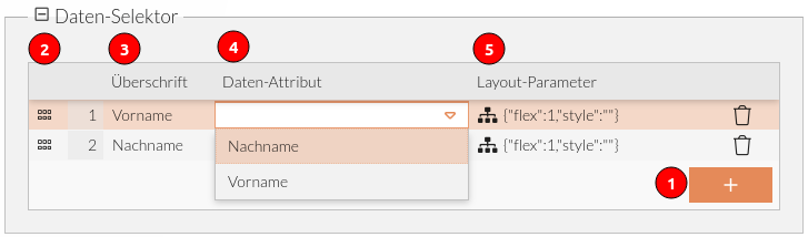
Daten-Selektor - Tabellenspalten hinzufügen
[
    {
        "Vorname": "Max",
        "Nachname": "Mustermann"
    },

    {
        "Vorname": "Franz",
        "Nachname": "Müller"
    }
]
-
Add a column.
-
Drag-and-drop handle: Change the column order
-
Header: Desired text as the header in the column header
-
Data attribute: Selection field with attributes from the dataset
-
Layout parameters: JSON field with additional style parameter
Styling
The background color and text color of the table header can be controlled using CSS attributes.
{
  "flex": 1,
  "style": "color:red; background-color:green"
}
Diagram Export
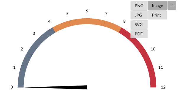
For the diagrams Tacho Diagrams (Gauge Diagrams), Pie Charts, and Line and Bar Charts (XY Charts), users have the option to enable exporting.
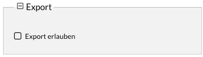
If this option is enabled, a menu appears in the upper-right corner of the diagrams. This menu allows you to export the diagram in various file formats.