Developing a Web Application in INUBIT Workbench
|
You require licenses for web applications in the portal and to use the task generator! These components are not covered by the standard license. You can find example programs for all tutorials in the INUBIT software. |
Prerequisites
-
You have installed the INUBIT Process Engine & Workbench set.
-
You have added a valid license.
-
You have logged in to the INUBIT Workbench with the user miller in order to access to the example diagrams.
Workflow Management
Involving employees is often required and desirable for automated business processes.
User interaction as part of the Technical Workflow
Interactions with users are completely integrated into the Technical Workflows and are created through running workflows. The assignment of tasks arising from the process flow takes place on the basis of roles and can also be controlled using an organization diagram. This enables individual tasks to be assigned to a group of responsible parties. The organization diagram can also be used to determine a supervisor with whom a task can be escalated.
The processing of tasks takes place via a Web-based, personalized task list. A list of all tasks is displayed for each employee. This list is configured using the task generator module in an integrated WYSIWYG editor.
The list structures the tasks of the user and delivers any required additional information such as the priority of the tasks. External applications such as MS Office can also be integrated.
The Process interaction is a JSR 168-compliant module and an integral part of the BPC.
Creating portals
You can also implement complete portals on the basis of the Technical Workflows and in conjunction with the task generator. The Technical Workflows define the logic required to determine the page sequence and to exchange data with back-end systems. The task generator module defines the individual pages, which also contain the portal navigation elements. The tight connection with the business process diagrams means that a portal can be created in a completely process-oriented manner with the INUBIT software.
Refer to
Developing Your Own Web Application
This section describes how to create a form-based Web application for processing orders at the car dealership.
Requirements
The portal server is activated and the portal is configured as process user server (refer to Configuring the Portal Server).
Basic procedure
-
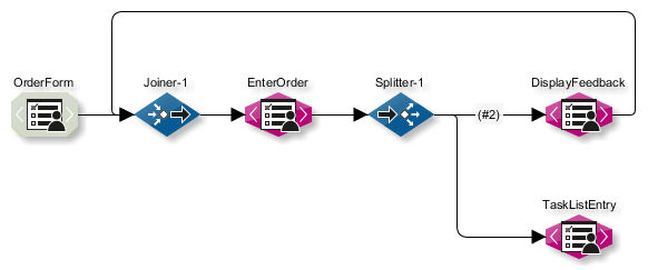
Create a Web application as a Technical Workflow
Consisting of:
-
Web application Input Connector
This connector makes the functions of the Technical Workflow available as a web application instance in the portal. All properties that are relevant for the entire Web application, such as application permissions or timeouts, are configured on this connector.
As soon as the Web application Connector is deployed on the portal server, a web application instance is generated. This instance serves as a user interface for the Web application. In addition, all relevant information, such as application permissions, is transferred to the portal server.
-
Two task generators with the task type Form sequence/Web application page
For generating the order and feedback form.
-
One joiner and one splitter in each case.
-
Task generator with the task type Item in task list > Task
Each new order should generate an item in the task list of the responsible employee.
The order is submitted to the employee for approval/rejection.
-
-
Activate and publish the Technical Workflow.
Only web application instances based on active Technical Workflows are displayed in the portal.
-
Deploy the module instance.
-
Assign application permissions in the portal to one or more roles.
Creating the Web Application Connector
Proceed as follows
-
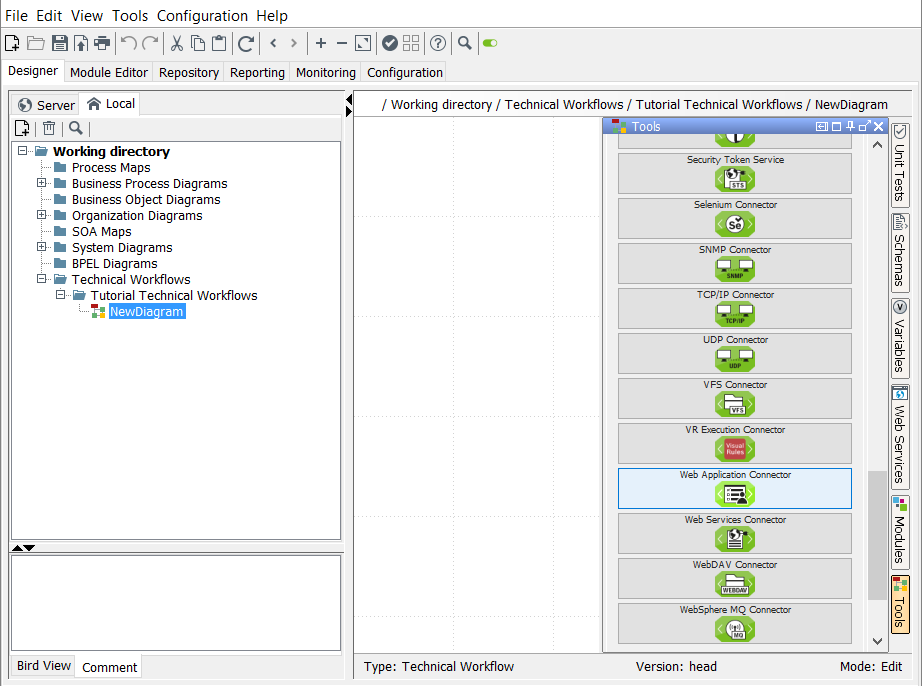
Create a diagram of the type Technical Workflow.
-
Insert a Web Application Connector from the System Connector group in the sidebar into the diagram:
The module wizard opens.
-
In the first dialog, enter a name for the module.
-
Click Next.
-
Select Input Connector for Connector type.
-
Select Active for the connector.
-
Click Next.
The following dialog is displayed: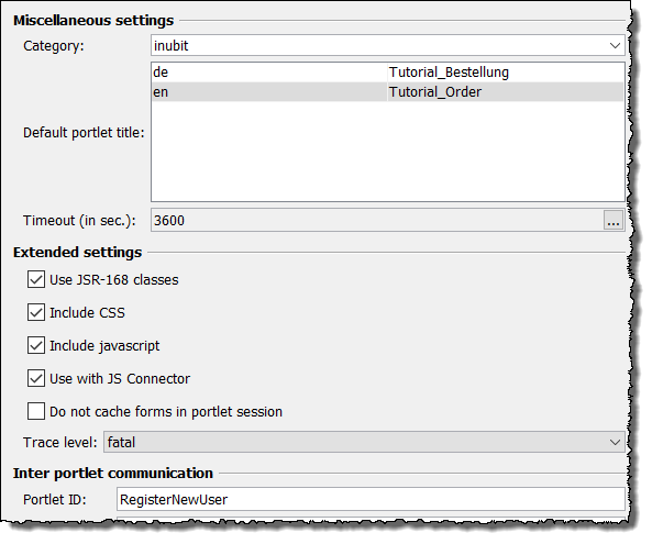
Enter a portlet ID.
-
Click Next.
-
Skip all of the subsequent dialogs and close the wizard by clicking Finish in the last dialog.
-
Insert a joiner from the Workflow Controls group in the sidebar, enter a module name and connect it with the Web application Connector.
The joiner is required to create the messages in the form of a loop so that an empty form is displayed once each order has been submitted.
Creating the Task Generator
Proceed as follows
-
Insert a task generator from the Data Converter group in the sidebar:
-
Enter the module name in the first dialog.
-
Click Next.
-
In the dialog that now appears, select Form sequence > Web application page.
-
Click Next.Skip the Permissions dialog.
-
Click Next.
-
In the XSLT Mapper settings dialog, select Ignore input message, since the input data is entered by the user directly into the form rather than coming from a previous module.
-
Click Next.
-
In the dialog Panel Layout select the layout template Table Layout.
All form elements will be arranged in a table because that makes it easier to position them.
-
Confirm with Finish. The task generator is displayed in the designer workspace.
-
-
Connect the task generator with the joiner you just added.
-
Open the context menu of the Task Generator and select Edit (in module editor).
The Task Generator > Form Mapping tab opens. In the Designer (bottom right) a small table is displayed which is represented as XML element Panel with an
orientation='table'attribute on the Form mapping > XML target area (top):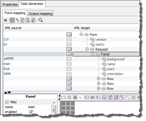
The next sections illustrate how to create the order form with the so called order mapping on this tab.
Creating the Form Mapping 1: Inserting Labels for Input Fields
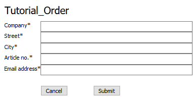
The order form should look like this:
Proceed as follows
-
Create labels for input fields:
-
Drag a label element
 from the form designer toolbar and drop it onto the first table cell:
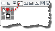
The red border indicates where the label is to be inserted.
This inserts a
Labelelement on the Form mapping > XML target tab. -
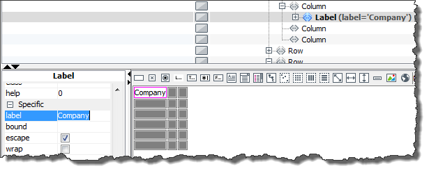
Click the label in the designer. A colored frame appears around the label and the properties of the label element are displayed on the Properties tab.
-
To provide text for the label, enter Company in the Specific > label line area of the Properties tab. Confirm your entry by pressing Return. The word you entered is now displayed in the designer and in the XML source/target area:
-
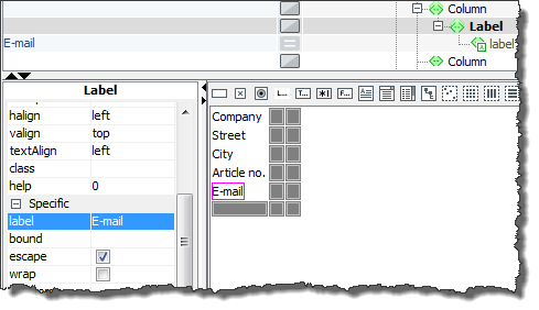
Repeat the procedure for inserting and naming a label for the other four label elements. Insert each label into an empty table cell. Enter an asterisk (*) after each label name. This informs users who fill in the form later on that all fields are mandatory and must be filled in.
To insert additional table rows, open the context menu for the table and select Insert row.
If you select a table row and then insert another row, the selected table row is copied. This make it easier to create elements that are required frequently.
-
-
Create input fields, name them, and mark them as mandatory fields
-
Drag a TextField element
 from the toolbar and place it in the empty table cell next to the Company label:
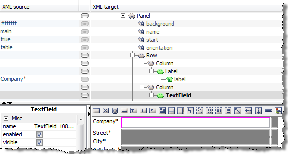
-
Insert TextField elements next to the other labels in the same way.
-
Assign names to the input fields so that they can be identified more easily when being analyzed: To do so, select the first input field and display the Properties tab. In the General area enter the value Company for the
nameattribute: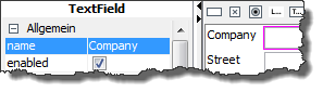
Make sure that the value of the
nameattribute complies with the naming rules for XML elements. -
Select the mandatory checkbox. This marks the input field as a mandatory field.
-
Repeat the last two steps for all other input fields.
-
-
Use the context menu to delete the empty table column.
-
To display the preview, click
 in the INUBIT Workbench toolbar.
The form should look like the following:
in the INUBIT Workbench toolbar.
The form should look like the following: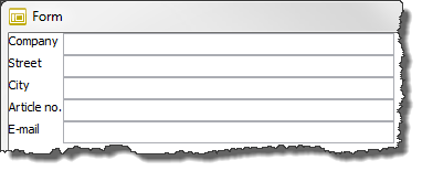
Creating the Form Mapping 2: Adding Buttons
Proceed as follows
You still need buttons for sending the order:
-
Insert another two table rows.
-
Drag a button element
 onto the form and place it in this last, empty table row.
 -
Place a second button next to the first:
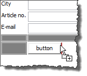
Pay attention to the red mark. It shows you where the second button is being placed.
-
To increase the gap between the two buttons, insert a horizontal filler
 between them.
To define the width of the gap, select the filler and enter a pixel value for the
between them.
To define the width of the gap, select the filler and enter a pixel value for the sizeattribute in the Specific area of the Properties dialog. Example: 50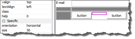
-
Select a button and display the Properties tab.
-
Name the button by entering
label=Submitin the Specific area. -
Below this, select the
submit(value) event, since you want the input data to be submitted when the button is pressed. -
Beneath the event, select the validate checkbox. The system will now check that all fields marked as mandatory are filled in before the Submit button is activated:
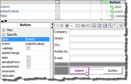
-
Assign the values
label=Cancelandevent=cancel()to the second button.→ The input form is now complete. In the next step, you define how data that users enter into the form is forwarded to the next module in the workflow.
Creating the Output Mapping
You use output mapping to define the data structure that is forwarded to the next module in the Technical Workflow.
Proceed as follows
-
Click
to display a preview. -
Enter data into the fields so that you can submit the form.
-
Click Submit.
The Output mapping tab appears. The XML source file area (bottom left) displays the XML data that is generated when you click Submit and sent to the task generator module:
-
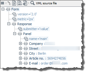
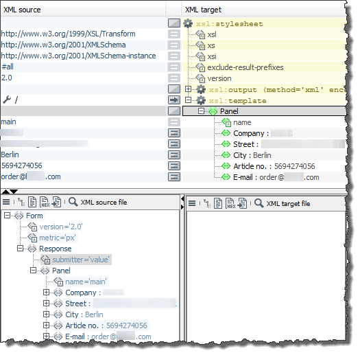
In the XML structure, navigate to the Panel element and drag it from the XML source file tab diagonally upwards into the XML target area and drop it onto the template element. The structure is copied to the style sheet along with all child elements (right) and the data (left):
-
Adopt values from elements
Naturally, you do not always want to display the static data displayed top left; instead, you want to display the current values entered for the form elements.
-
To do so, delete the values displayed in the XML source area (top left): Select the cell and double-click it. Remove the value and confirm the change by pressing Return.
-
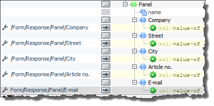
Drag the
Companyelement from the XML source area (underForm > Response > Panel) to the top left and drop it into the empty row next to theCompanyelement.A context menu opens.
-
Select Assign value (value-of) from the context menu.
The XPath expression
/Form/Response/Panel/Companyis displayed in the field.Proceed in the same way for all other elements in the form. The result should look like the following:
You have now completed the output mapping.
-
-
Click
 to test the output mapping.
The result is displayed on the Mapping results tab (bottom right). The generated XML structure and the data is passed from the task generator to the subsequent module (the splitter) when the Technical Workflow is processed.
-
Publish the module.
Publish your module after important configuration steps such as defining form mapping. This allows you to save different work states, because a new version of the module is generated each time you publish it. You can access versions whenever you want.
Inserting Additional Modules 1: Creating a Splitter
Proceed as follows
-
Display the Technical Workflow again.
-
Insert a splitter (Workflow Control group):
The splitter duplicates incoming orders:
-
One order is forwarded to the task generator that displays the feedback form.
-
The other order is passed on to the task generator that generates a task list item.
All orders are simply forwarded by the splitter; they are not processed further.
-
-
Connect the splitter with the task generator.
Inserting Additional Modules 2: Creating a Task Generator for Order Feedback
Proceed as follows
-
Create the task generator for order feedback.
Once the order has been submitted, a short message should tell the ordering party that the order is on its way.
-
Create another task generator module.
-
Select the Form sequence > Web application page option again. The application permissions do not need to be taken into account in this module, either.
-
Select General > Ignore input message in the XSLT Mapper settings dialog.
-
Close the module wizard by choosing Finish.
-
Open the module for editing.
-
Generate the following form using a label and a button in the designer:
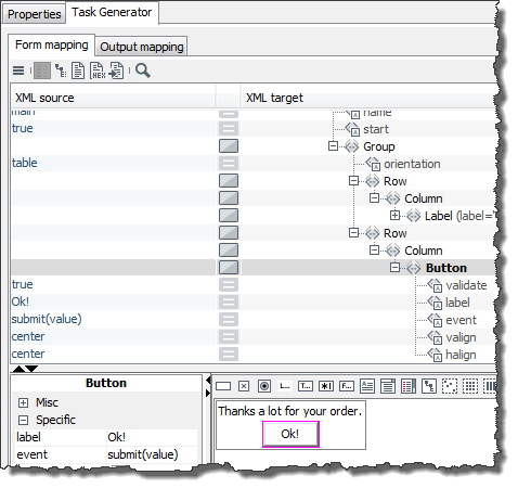
-
Define any output mapping, that you can freely select, e.g.:
The output message of this task generator is not used any further. Therefore, structure and content of the message are not relevant.
-
-
Display the Technical Workflow.
-
Connect modules:
-
Connect the splitter with the task generator you just created.
-
Connect the new task generator with the joiner.
This connection ensures that an empty order form is displayed to users after they click the OK button in the feedback form.
-
Inserting Additional Modules 3: Creating a Task Generator for Items in the Task List
Proceed as follows
-
Create a task generator for the item in the task list. Each new order should be displayed in the task list of the responsible employee so that the order can then be approved manually.
-
Create another task generator module.
-
Fill in the Task Generator Properties dialog as follows:
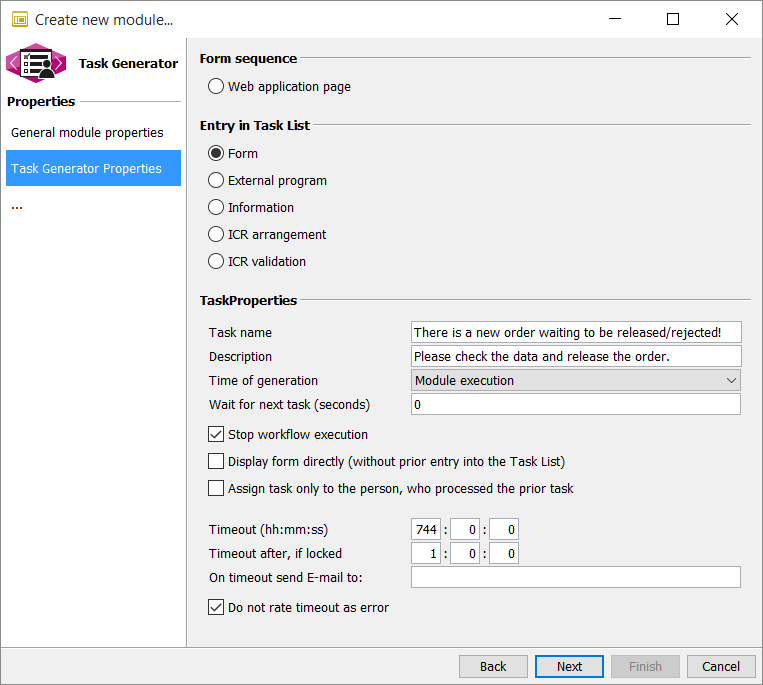
-
Click Next.
-
In the Permissions dialog, specify that the Administrator and User portal roles should be used.
This causes the task to be displayed to all owners of these roles. The task is deleted from the task list as soon as one of the role owners processes it.
Portal roles are only displayed if a portal server is active, a portal is available, and the portal is configured as process user server, refer to Configuring the Portal Server.
-
Click Next twice and while doing so, ignore the dialog XSLT Mapper Settings.
-
In the dialog Panel Layout select the Table layout and then click Finish.
-
Open the module for editing and create the following form in the designer:
-
To ensure that the order cannot be changed, deactivate the
enabledattribute for all labels and properties in the Misc area. -
Remember to name the display fields using the
nameattribute.
-
|
You can facilitate your work routine by copying the form you created in the Task Generator EnterOrder and pasting it here. |
-
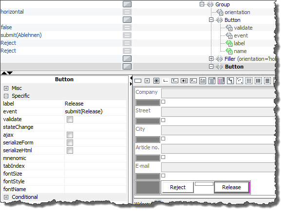
Both buttons receive a
submitevent. In this case, it is important to differentiate between the two buttons. You should therefore enter the following event values:-
submit(Reject) -
submit(Release)Confirm your entries by pressing Return.
The event values help to identify which button was clicked. They are passed to the subsequent module once either button is clicked. Further processing of the order may depend on the event value. For example, an order with the event value Approve may be passed to the responsible department. This is not part of this tutorial.
For more information on using JavaScript, refer to Using JavaScript in Forms.
For more information on using JavaScript to submit a form when having configured a BPC portal, refer to Using JavaScript to Submit a Form in the BPC Portal.
For submission of forms in a BPC webapp, the following function can be used:x
Ext.getComponent(bpcComponentId).submit(event,namespace,url);event: submit event from button or nullnamespace: namespace used in form or''(empty)url: URL for submission
-
Inserting Additional Modules 4: Creating another Form Mapping
Proceed as follows
-
The module receives the order data from the form as an input message. You have to map this order data to the form for the task list entry. For this mapping, you need an output message from the first task generator module:
-
Display the Technical Workflow.
-
Select the first task generator.
-
Open the context menu and select Edit (in module editor). The order form is displayed in the designer.
-
Click
to display a preview. -
Fill in the fields and click Submit. The form preview closes and the Output mapping tab is displayed.
-
Test the style sheet: Click the
button.
The result is displayed on the Mapping results tab. -
Click the
 button and copy the result to the clipboard.
 -
Now, display the form for the task list entry in the Designer again.
-
Display the Source tab at the bottom left.
-
Click the
button and select Open > Clipboard.
The result you just copied is displayed. -
Expand the structure.
-
Select the Company text field in the designer. The corresponding XML structure is displayed in the XML target area.
-
Drag the
Companyelement from the Source tab up to the XML source area and drop it into the row to the left of theTextFieldelement that is formatted in bold. A context menu opens. -
Select Assign value (value-of). This specifies that the value of the
Companyelement is to be displayed in the selected display field. The result should look like this: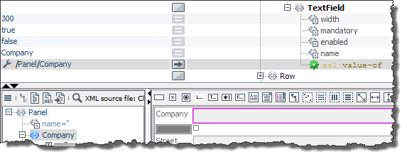
-
Repeat the last two steps for all other elements in the form.
-
Click
to display the preview: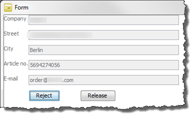
-
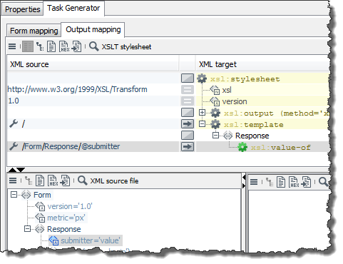
Click Release. The Output mapping tab appears. The XML data created when you clicked the button appears at the bottom left.
The current status of the order is identified by the attribute value
submitter=Releaseof theResponseelement.If the order had been rejected, the value would be
submitter=Reject. -
Create any kind of output mapping.
The output mapping is not required in this tutorial because the workflow ends with this module. However, an output mapping must exist or else you cannot publish the module.
Drag any element, such as a Panel element, from the XML source file tab diagonally upwards to the XML target area and drop it onto the template element.
-
Publish the module.
-
-
Display the Technical Workflow.
-
Connect the task generator you created most recently with the splitter.
-
Publish the Technical Workflow.
-
Activate the Technical Workflow by selecting it in on the Server tab, opening the context menu, and choosing Activate. The workflow symbol now appears with a colored background:
→ Your Web Application is finished. You can now add it to a portal page as a web application instance.
Adding a Web Application to a Portal Page as an instance
In this section you learn how to add your Web Application to the BPC Portal as a portal instance on a new page within a password-protected area.
Granting Web Application Permissions, Assigning Them to Portal Roles
To control the use of your web application, you can grant special application permissions to buttons and input fields. Then, only Portal users with roles to which these application permissions were assigned in the scope of their site, are able to make use of those web application controls.
Requirements
You are logged in to the portal as an administrator.
Proceed as follows
-
In the INUBIT Workbench, display the Technical Workflow that you created in a previous chapter.
-
Open the Web application Connector for editing. The module wizard opens.
Defining Permissions
Proceed as follows
-
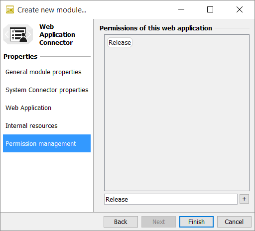
Click through the dialogs until you reach the Permission management dialog.
-
Beneath the display field, enter Release.
-
Click the Plus button to copy the permission to the display field:
-
Click Finish.
-
-
Publish the Web application Connector to transfer the permission you just defined to the task generator.
-
Open the last task generator for editing; this is the task generator that creates the task list entry. The task generator is selected in the module tree (left).
-
In the module tree, open the task generator context menu and select Edit properties. The module wizard opens.
-
Click through the dialogs until you reach the Permissions dialog.
-
Adopt the application permissions from the OrderForm Web Application Connector by selecting the checkbox in the Web Application Connector section. For creating the Connector refer to Developing Your Own Web Application.
-
Click Next and then click Finish to close the module wizard.
Assigning Permission to Form Element.
Assign the Release permission to the button.
Proceed as follows
-
Select the Release button.
-
Click the empty cell next to the
enabledattribute in the Conditional area of the Properties dialog. The Select permissions dialog appears: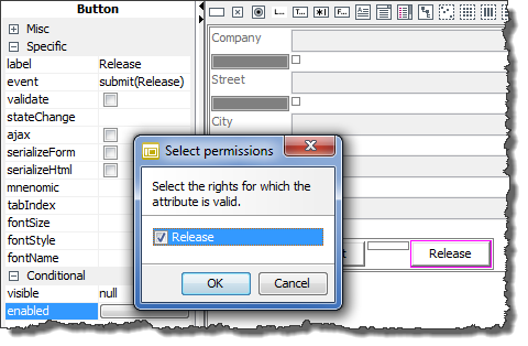
-
Select the Release option.
-
Click OK. The dialog closes.
-
The cell now contains
{p:hasPermission($ISPortalUser, ’Release’)}and the button has a colored border. -
From now on, the button is only active in the portal for users to whose role the permission Release is explicitly assigned.
-
Publish the module.
Re-Deploying the module instance
Re-deploy the module instance to make the property changes available.
Proceed as follows
-
In the INUBIT Workbench, display the Administration > General Settings tab.
-
Open the configuration area Portal > Portal Deployment.
-
At the option Portlet-Archive click Open
.
A dialog opens. -
In the area Archives on portal server in the column Action click Redeploy archive
 icon.
icon. -
Confirm the next dialog.
-
The deployment starts. A dialog with a progress bar is displayed.
-
After the deployment has been finished successfully, this dialog is closed automatically.
-
Close the dialog.