System Diagrams
Usage
This diagram type allows you to graphically model the IT landscape of your own systems and those of your partners.
If you use several system connectors of the same type, you can configure the connection parameters of these system connectors centrally in your system diagram.
By using the partner management, you can receive messages from different partner systems via different communication channels and treat them to process and send them in a uniform manner.
Refer to Partner Management.
Linking system diagrams
-
Linking system diagrams with other system diagrams
In a system diagram, you can link the modeling elements Partner, External system and Communication cloud to other system diagrams. This provides the opportunity to model a summary view in one system diagram and link it afterward to several detailed views of th IT landscape.
-
Linking system diagrams with organization diagrams
For documenting persons responsible for systems, you can link elements in organization diagrams with the following elements in system diagrams: External system, Partner and User task.
Refer to End-to-end Navigation between Diagrams.
General diagram functions
In system diagrams, too, you can use the general diagram functions, refer to:
Managing the Connection Parameters Centrally
External systems such as, for example, INUBIT Process Engine, e-mail servers, databases or file systems are linked to Technical Workflows using system connectors.
You can use system diagrams to centrally administer the connection parameters of several system connectors of the same type as well as Complex Lookup Tables.
|
You can configure in system diagrams, the connection parameters that are to be managed centrally. You can add INUBIT-owned and self-developed system connector types or Complex Lookup Tables as well as edit them and add them to the connection parameters of already existing system connectors or Complex Lookup Tables. |
Prerequisites
Your system diagram contains one or more external system diagram elements.
Proceed as follows
-
Open the system diagram for editing.
-
Select the diagram element for the external system whose connection settings you want to edit.
-
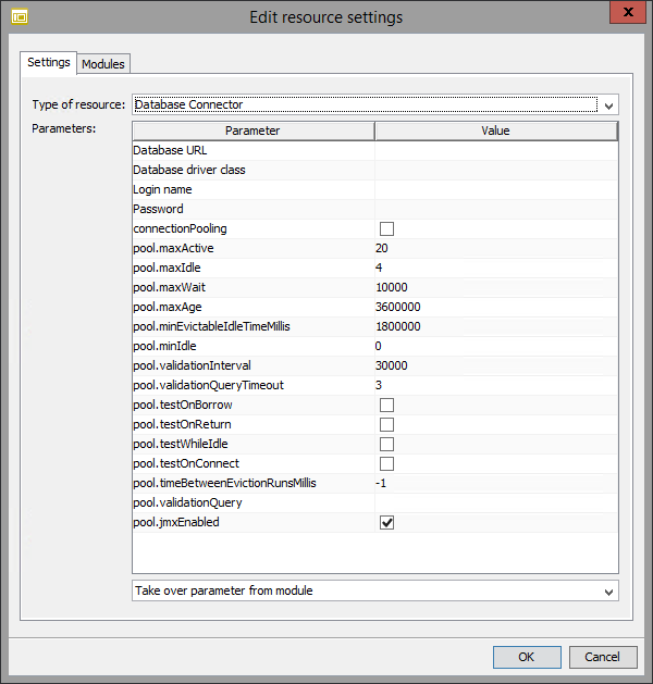
Open the context menu then select Edit resource settings.
The following dialog opens:
-
Select the system connector type or Complex Lookup Table and set the central parameters:
-
Select the type of the system connector from the Type of resource drop-down list. The list contains all the system connector types and the Complex Lookup Table that are visible to you.
-
Specify whether you want to set the connection parameters manually (Parameters area) or copy from an already configured module.
-
Setting parameters manually
Fill in the fields in the Parameters area.
-
Take over parameters from module
In the drop-down list, select the module from which the parameters are to be copied.
Input Listener Connectors are not supported and, thus, cannot be selected.
-
-
-
Specify the modules to which the connection parameters are copied:
-
Display the Modules tab. A list is displayed showing all modules of the type selected.
-
Select the modules the specified parameters are to be assigned. This enables the icon
 .
. -
Click the icon
.
The dialog Select processing rules opens. -
Choose the rules you want the respective module to be assigned with from the individual list of available rules. When doing so you should take to account the following:
-
Rules which are not selected in the system diagram will not be executed.
-
A rule cannot be enabled in more than one system diagram or external resource tool.
-
If a rule is linked to a system diagram, it cannot be renamed while editing the Complex Lookup Table.
-
If a Complex Lookup Table is being linked to a system diagram for the first time, all rules will be linked by default.
-
-
-
Click OK to end the configuration. The dialog window closes.
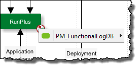
→ A connection symbol is displayed on the external diagram element. This symbol indicates that the diagram element manages the connection parameters of system connectors or Complex Lookup Tables in one or more Technical Workflows.
If you open the context menu for the connection symbol, a list is displayed showing all the system connectors or Complex Lookup Tables administered.
Partner Management
Usage
Using partner management you can integrate large numbers of external business partners into the supply chain and thus into your company’s business processes.
The partner management helps you performing the following tasks:
-
Receiving messages from various partner systems via different communication paths, like HTTP, FTP, POP3, AS2.
-
Partner-specific editing of messages in order to process them in a uniform way.
-
Sending messages to partners exactly in those formats and via those communication paths the partners expect.
Separation between technical data and partner-specific data
Partner-specific master data (for example, contact data) and communication parameters (for example, URL, server names and accounts) are stored centrally on business process level while the technical details (like data formats and protocols) are configured on the technical process level.
This separation offers the following advantages:
-
It allows companies to reduce load on their IT departments. Once the technical configuration has been completed, any further maintenance of partners' reference data can be undertaken by the relevant specialist department, such as Purchasing or Logistics, without the need for any technical knowledge.
-
The technical processes can be structured uniformly and independently of the actual partner, so that the complexity of the partner networks remains manageable.
-
Both the business and technical processes can be quickly adapted to changes in requirements and expanded to include new partners.
Supported protocols
All protocols the partner management supports are listed in the file partnermanagement_config.xml.
|
After import it or migration from an older INUBIT version (< 7.0), the file |
Functional Principle of the Partner Management
You can depict your complete partner net with all partner master data and communication parameters for inbound and for outbound scenarios in a system diagram by using the element communication cloud.
-
Partner master data
These are name and ID of a partner. You can add further configurable fields, for example to store telephone numbers.
-
Communication parameters
These are, for example, the URL of your partners’ servers and the login data which are required for connecting to them.
Partner master data and communication parameters are available as workflow variables in Technical Workflows.
The partner net is linked to all Technical Workflows which pre-process input messages from partners or output messages for partners.
Inbound scenario
In order to receive partner messages from different systems in a Technical Workflow, all required input system connectors are inserted into a partner management element.
This partner management element is linked to the partner net in the system diagram. Each time the Technical Workflow is executed the communication parameters stored at the system diagram to dynamically select the system connector which matches the input message.
Messages are fetched/send in sequence from all configured partners, depending on the system connector type. As a principle, all messages from one partner are fetched/send before the messages of the next partner are processes. In case an error occurs, processing is continued with the next partner.
When configuring the partner management element you can extend the existing parameters (like formats or protocols) arbitrarily, for example for adding encoding information.
When receiving messages, for each messages a system variable ISPartnerID is created, filled with the appropriate value which was stored in the system diagram manually and handed over to the message flow.
You can use
ISPartnerID for partner-specifically controlling the further message flow, for example, by converting non-uniform input messages in such a way that they become available in a normalized format for further processing after the partner management element.
Outbound scenario
In an Outbound scenario all outgoing messages run into a partner management element, which is linked with the partner management element in the system diagram.
In the partner management element, the partner IDs are read out of the messages or the system variable ISPartnerID
and the partner master data matching these IDs (like the message format the partner expects) from the system diagram.
Then, the output messages are converted into the format the respective partner expects and are sent via the protocol which is suitable for the respective partner.
Refer to
Configuring Technical Data in an Inbound Scenario
Requirements
-
All system connectors must be input system connectors
-
HTTP, RosettaNet, AS2 Connectors, and JMS Connectors are configured as listeners
-
For File and FTP Connectors the schedulers are activated
Proceed as follows
-
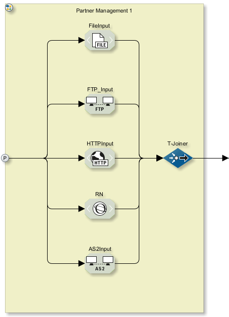
Create a Technical Workflow with more than one system connector; for example, a file input connector, an FTP Connector and an HTTP Connector.
-
Drag a partner element off the sidebar onto the Technical Workflow.
-
Drag the system connectors onto the partner element.
-
Connect all the system connectors to the partner element’s P symbol.
-
Join the messages of the system connectors:
-
Insert the workflow control Joiner.
-
Drag the Joiner onto the partner element.
-
Connect each system connector with the Joiner.
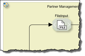
Your Technical Workflow should now look like this:
-
-
Double-click the partner element’s P symbol. The dialog is displayed. Refer to Partner Management Configuration.
-
Define the basic settings for the partner management:
-
Select the Inbound type.
-
Enter all the message formats and protocols that are supported by the system connectors you have used.
-
Click OK to close the dialog.
-
-
Publish the Technical Workflow.
Providing Partner Master Data and Communication Parameters
Proceed as follows
-
Display your system diagram in the local mode or create a new system diagram.
-
From the sidebar, open the Tools docking window and drag the element communication cloud onto the working area.
-
Open the context menu of the communication cloud and select Edit partner management settings.
The dialog opens. Refer to Partner Management Settings.
-
Creating partners:
-
Open the context menu of the partner table.
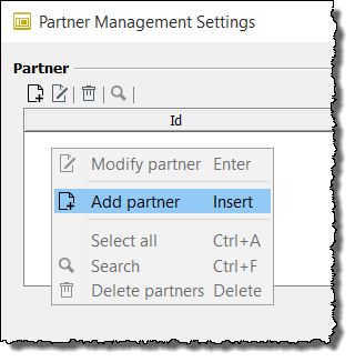
-
Select Add partner. A dialog opens.
-
Enter the name of the partners and a unique ID. If you use an AS2 Connector, enter here the AS2 ID of the respective partner/s. Refer to Partner Management Settings.
-
Click OK to close the dialog. The new partner is displayed in the table and the Referenced workflows area is displayed.
Repeat these steps for each partner.
-
-
Adding referenced workflows:
You can add all Technical Workflows in one step to the partner management and assign them later to the various partners.
-
In the Referenceable workflows docking window, open the context menu:
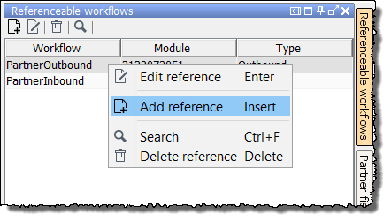
-
Select Add reference. A wizard opens which guides you through the process of selecting a Technical Workflow. The selected Technical Workflow is displayed in the table. Repeat these steps for each Technical Workflow.
-
-
Linking partners with Technical Workflows and defining the protocol and format which is expected by the partners
-
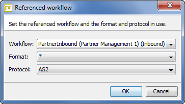
Open the context menu of the table Referenced workflows and select Add referenced workflow. The following dialog is displayed:
-
Select the workflow which will process the partner messages.
-
Select the message format which the partner sends or expects (depending on whether the Technical Workflow implements an inbound or outbound scenario).
-
Select the protocol which is appropriate for the partner.
Which message formats and protocols are offered for selection, is defined when configuring the partner elements in the Technical Workflow.
-
Click OK to close the dialog.
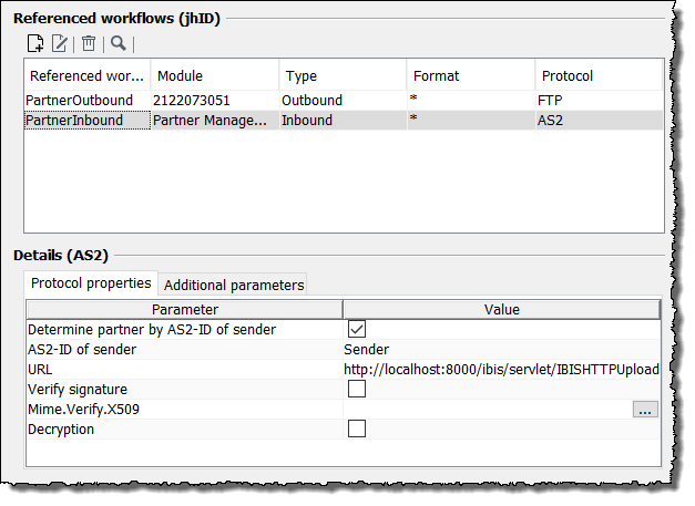
The Details area is displayed:
-
-
In the Details area, enter the format-specific settings for the currently selected referenced workflow, e.g., the URL where the AS2 Connector is waiting for messages.
-
In an inbound scenario, the settings are automatically applied to the input system connectors.
With an AS2 Connector as Listener you can use the AS2-ID instead of the URL as unique identifier for the partners. Enter here the AS2-IDs that your partners must communicate to you and use for all AS2 partners the same URL, which the AS2 Connector needs to receive messages. This URL must correspond to the one that you configure in the Listener module configuration dialog. The URLs of AS2 Connector modules (inbound/outbound) which are configured in Partner Management cloud must be unique.
In order to assign the AS2 Inbound connections to a partner, the AS2 ID is used by default: Enter the value for the AS2 ID of sender as well as the URL of the AS2 connection.
For compatibility reasons, you can use the respective AS2 ID as partner ID as distinguishing feature to assign the partner. To do this, you must disable the Determine partner by AS2-ID of sender.
The Determine partner by AS2-ID is only considered if the Partner Management URL is same as the listener URL.
-
In an outbound scenario, the settings do not directly apply to the output connectors. Therefore, they must be set at all individual connectors by means of variables mapping.
The value of the Directory and file name parameter in an outbound scenario (refer to Configuring Technical Data in an Inbound Scenario) is written to the `ISPartnerProtocol.FileName `variable and can be assigned by using the variables mapping of the module property `FileName `in a File Connector.
-
-
Click OK to close the dialog.
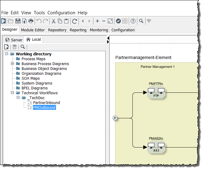
→ In the bottom right corner of the communication cloud element a link point is displayed:
Navigating
When you double-click the link point in the communication cloud element, a list of all Technical Workflows is displayed which are now linked to the system diagram. A link point is also displayed in the Technical Workflow:
+
By double-clicking the link, the system diagram is displayed again.
Configuring Technical Data in an Outbound Scenario
Prerequisites
-
The Technical Workflow in which the actual message processing takes place already exists.
-
The appropriate partner ID must be present either in the messages or as variables in the message flow so that the messages can be assigned to the correct partner in each case for transmission.
Proceed as follows
-
Display the Technical Workflow in the local directory.
-
Drag a partner element onto the workflow.
-
Double-click the P symbol. A dialog is opened in which you configure partner management for the outbound scenario.
-
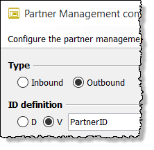
Select the Outbound type.
-
Specify whether the partner ID comes from the messages or is passed as the value of a variable (option D or V).
For example:
-
-
Connect the last module of your workflow to the partner element’s P symbol.
-
Insert a Demultiplexer and drag this onto the partner element.
-
Connect the partner element’s P symbol to the Demultiplexer.
-
Insert a module that is to perform the format-specific processing of the message, and connect this to the Demultiplexer.
-
Insert a Joiner and connect the format-specific processing module to the joiner.
-
Insert a further Demultiplexer and connect it to the Joiner.
-
Insert the system output connectors that are to dispatch the messages.
-
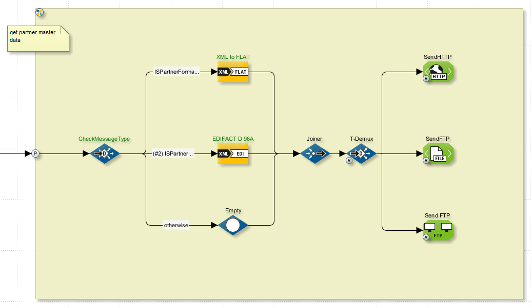
Connect the system output connectors to the Demultiplexer. The Technical Workflow should now look approximately as follows:
-
Publish the Technical Workflow.
-
Link the Technical Workflow to the partner net in the system diagram.
-
Test the Technical Workflow.
-
Double-click one of the test points after the first multiplexer to display the names of the variables that have been passed. For example
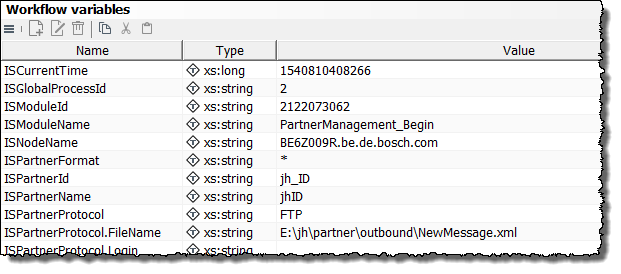
The list includes the two variables
ISPartnerFormatandISPartnerProtocol. The values of these variables depend on the partner reference data and communication parameters currently being used. -
Define the ISPartner-Variablen initially to be able to use them in the next steps.
-
Open the technical workflow for editing.
-
Test the technical workflow and display the workflow variables at a watch point.
-
Announce the ISPartner variables to the technical workflow by clicking the particular link
Define variable. -
Publish the technical workflow.
-
-
Now configure the connections for the two Demultiplexers:
-
Open the connections for the first Demultiplexer one after the other and assign a format to each of them. To do this, insert the condition
ISPartnerFormat=FLATorISPartnerFormat=EDIFACT D.96A. -
Follow the same procedure for the connections for the second Demultiplexer. In this case insert the conditions
ISPartnerProtocol=HTTPorISPartnerProtocol=FTP. Refer to
-
-
Configure the variable mapping of the output connectors. For every property set in the partner management, a variable named
ISPartnerProtocol.<Name of property>is created, e.g. when configuring a file connector, the variable namedISPartnerProtocol.FileName `or for an AS2 connector the variables named `ISPartnerProtocol.ServerName,ISPartnerProtocol.ASFromandISPartnerProtocol.ASTo.-
Open the variable mapping of the output connector.
-
Define a mapping for each parameter.
-
As source type, select Variable.
-
Select the corresponding variable with the prefix
ISPartnerProtocol.or create it. -
As target type, select Module property.
-
Select the corresponding module property.
-
Click OK to save your changes.
-
Dialog Descriptions in the Partner Management
Partner Management Configuration
Call Up
In Technical Workflows with a partner element, after double-clicking on the partner element’s P symbol.
Type
-
Inbound
For receiving messages.
-
Outbound
For sending messages.
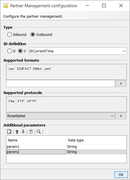
ID definition
(Only displayed if the Outbound type was chosen)
For defining the source from which the partner ID comes. The partner ID is used for the assignment to the partner-specific communication parameters.
-
D: The partner ID comes from the content of the messages.
The path to the partner ID must be specified as an XPath expression. If you have a message with the same XML structure as the messages that are to be sent, click the
 button to navigate in the message to the element containing the partner ID.
This gives you the XPath expression.
button to navigate in the message to the element containing the partner ID.
This gives you the XPath expression. -
V: The partner ID comes from a variable that is passed on with the message flow; for example, from the
ISPartnerIDsystem variable.Enter the variable name or select one from the drop-down list.
The variable can come from the following sources:
-
it was set manually via the variable mapping in the Technical Workflow
-
or automatically completed if partner management has already been used to receive the messages. An
ISPartnerIDvariable is created for each message when it is received and is passed on in the message flow. The value is specified manually when partner management is configured.Refer to Partner Management.
Supported formats
The supported formats must be specified so that they can be assigned to the various partners in the system diagram when partner management is configured.
-
Adding
-
Enter a supported format.
-
Click the +-symbol.
→ The format is displayed in the gray area. Repeat these steps for each format that is supported by your partner management system
-
-
Deleting
-
Select a format in the gray area.
-
Open the context menu then select Delete.
→ The format is deleted from the gray area.
-
Supported protocols
The supported protocols must be specified so that they can be assigned to the various partners in the system diagram when partner management is configured.
-
Adding
-
Select a supported format from the drop-down list.
-
Click the +-symbol.
→ The protocol is displayed in the gray area. Repeat these steps for each protocol supported by your partner management system.
-
-
Deleting
-
Select a protocol in the gray area.
-
Open the context menu then select Delete.
→ The protocol is deleted from the gray area.
-
Additional parameters
For defining any further parameters that are used to manage the partner’s reference data; for example, telephone number or name of contact.
The values of the parameters are specified during configuration of partner management in the system diagram.
Refer to Partner Management Settings.
Partner Management Settings
Call Up
System diagram > Context menu of the element Communication cloud > Edit partner management settings.
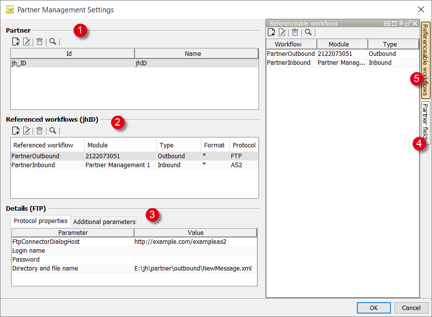
This dialog is used to maintain the partner master data, the communication parameters, and the Technical Workflows that send or receive messages to/from your partners.
|
All partner fields, properties, and additional parameters are available as variables during the workflow execution. |
-
Partner
Fields for maintaining partner master data. The master data is linked to the running technical instance of the system connector by the ID. In inbound scenarios, this ID is assigned to the variable
ISPartnerID. The variable is handed over to the message flow and used in outbound scenarios for matching output messages to the appropriate partners.With an AS2 Connector as Listener you can use the AS2-ID instead of the URL as unique identifier for the partners. Enter here the AS2-IDs that your partners must communicate to you and use for all AS2 partners the same URL, which the AS2 Connector needs to receive messages. This URL must correspond to the one that you configure in the Listener module configuration dialog. The URLs of AS2 Connector modules (inbound/outbound) which are configured in Partner Management cloud must be unique.
You can define further fields, refer to Partner fields below.
-
Referencable workflows
Area for assigning partners to Technical Workflows, protocols, and formats that are used for sending/receiving messages.
The lists contain the formats and protocols that were defined in the Technical Workflow at the partner management element.
Refer to Partner Management Configuration.
-
Details
-
Protocol properties tab
For defining actual communication parameters for the system connector which is used by the partner who is selected in the Referenced workflows area.
You can define which communication parameters are displayed in the file
partnermanagement_config.xmlby adding or deleting communication parameters (refer to Editing Configuration Files). -
Additional parameters tab
This tab displays all parameters defined in the dialog. Refer to Partner Management Configuration.
-
-
Partner fields
For creating further fields for maintaining partner master data.
-
Referenceable workflows
In this area, all the Technical Workflows which process incoming or outgoing messages are linked with the central partner management in the system diagram.
Opening Property Attributes
In case you want to change the attributes for filter settings, the property attributes can be opened and edited by clicking the A button.
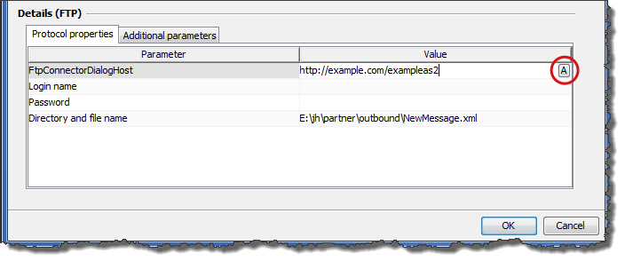
One example is the POP3/IMAP configuration of the partner management to edit the filters per configured partner.
There is a subject property with a condition attribute.
The attribute has to have the value filterContains or
filterContainsNot.
Modeling Elements in System Diagrams
Tools in System Diagrams
System diagrams may consist of the following elements:
| Symbol | Name | Meaning |
|---|---|---|
|
Partner element |
Partner system |
|
INUBIT system |
INUBIT Process Engine |
|
RC (Remote Connector) |
Remote Connector. |
|
External System |
IT system, for example, a database, a HTTP server or an e-mail server. |
|
User task |
For indicating that a system involves user interaction such as, for example, a task list. |
|
Communication cloud |
For indication the mode of communication between the systems, for example, Internet or TCP/IP. |
|
Firewall |
For indication that the systems between the communication cloud and partner system are protected by a firewall. |


Refer to Editing the Layout of Diagram Elements.
Artifacts in System Diagrams
In System diagrams you can use the following artifacts:
| Symbol | Name | Meaning |
|---|---|---|
|
Comment |
For adding a note anywhere on the workspace. |
|
Frame |
For visually grouping elements that belong together content-wise. Refer to Structuring Workflows with Frames. |
|
Image |
For inserting a graphic of your choice. Refer to Using Own Graphics as Symbols. |
|
Text |
For inserting user-specific texts that can be placed anywhere on the workspace. |


