Modeling Business Process Diagrams
Usage
Business process diagrams (BPD) enable you to model business processes according to established standards. The process modeling elements in the INUBIT software are based on the standardized Business Process Model and Notation 2.0 (BPMN).
BPMN supports you when registering and modeling business processes and is this primarily directed at business-functional users such as business analysts.
BPMN’s expressiveness enables users to map complex processes with a high degree of differentiation and has made it the de facto standard for business process modeling.
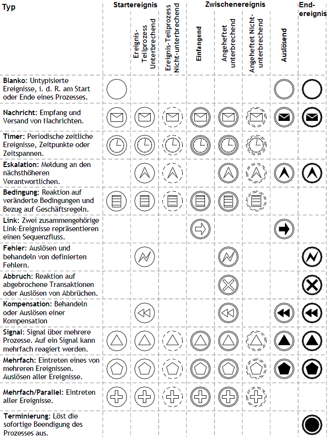
For the BPMN specification refer to https://www.omg.org/spec/BPMN/2.0/PDF. For an overview of the most relevant elements and concepts of BPMN 2.0 refer to BPMN 2.0 Poster.
Validating processes
You can let Business Process Diagrams validate. When validating the diagram’s syntax is checked, for example, whether all required labels exist and whether the element types and the message flow is correct.
Refer to Validating Diagrams - Syntax Check.
Creating Business Process Diagrams
Concept
To model a process, you insert a process-triggering event, model different process steps as tasks or sub-processes and display the end of a process with end events. Branches and merges in the process flow are represented by gateways, which control the process flow.
The steps involved in executing a business process are called tasks and sub-processes in the BPDs.
The term process is defined by BPMN as a set of tasks, sub-processes, gateways and events. A Sub-Process is an activity which in turn describes other activities whose process flow is represented in greater detail. A task is an atomic activity whose work is not described in detail.
You can define responsibilities for activities in which a process participant (e.g. an organization) is represented as a pool and the executing unit (e.g. a function, role or organization unit) is defined as a lane in the pool.
Creating BPDs
Refer to Creating a Diagram.
Inserting BPD elements
To map business-related processes using BPDs, enter some or all of the following elements in the newly-created BPD:
-
Events that start and stop the process
-
Tasks to be executed and their dependencies
-
Sub-Processes that sum up activities
-
Results of processes
-
Decision points
-
Additional information (artifacts).
To model processes in the diagram, use the modeling elements provided in the INUBIT software
The INUBIT software helps you create valid BPDs by, for example, only allowing you to insert permissible connections in the diagram:
-
When you click an element, a graphical context menu is displayed which shows the most important allowed elements that may be inserted at this point using drag & drop and also offers the option to change the type of the element.
-
Compliance with the BMPN rules for sequence and message flows is ensured through the selection of the correct element by the INUBIT Workbench. For example, if you want to connect tasks in different pools with each other, the system automatically displays a message flow and not a sequence flow.
Using profiles
You can use different profiles for creating Business Process Diagrams. Different subsets of the BPD elements for modeling are available in each profile.
Designing BPD elements
You can name the connections between elements and change their display as well as customize the layout of frames, comments or activities, etc.
BPD Modeling Elements
The INUBIT Workbench provides various types of modeling elements for process modeling in business process diagrams. These are described in the following sections.
In BPMN, tasks, sub-processes, events and gateways can also be referred to as flow objects.
Connections in Business Process Diagrams
You can use elements from the Connections group to display the connections between the business process steps, message flows connected to these and connections in conversation diagrams.
Sequence Flow
The sequence flow is the order in which the activities in a process are executed. The sources and targets of such connections are events, tasks and gateways.
|
Sequence flows can go outside the bounds of lanes within a pool, but cannot cross the border of a pool. |
| Type | Use | Icon |
|---|---|---|
Normal |
Sequence flow that connects the elements in a pool |
|
Conditional |
You can formulate conditions for when a sequence flow exits an activity. The conditions must be true for the flow to proceed. |
|
Default |
One of the sequence flows that exits an exclusive or inclusive gateway can be defined as the default output to be used when none of the other conditions are true. |
|


Message Flow
Illustrates the message flow between two participants in a process which are represented by two different pools in a diagram.
It is displayed by the following icon: 
|
Message flows are only allowed between pools, not within pools. |
Association
Associations connect tasks, sub-processes, events and gateways with artifacts.
| Type | Use | Icon |
|---|---|---|
Directed |
Indicates that a data object is an input or output of an activity |
|
Undirected |
Used to connect artifacts with elements of any type |
|
Bidirectional |
Indicates that a data object will be changed (read and written) during the execution of an activity |
|


Conversation Link
A conversation link connects communications with their participants:
| Type | Use | Icon |
|---|---|---|
Simple |
A simple conversation link connects the communication with its participant (pool). |
|
Forked |
Connects the communication with several participants of the same type, e.g. a group of graphic designers. The forked conversation link is automatically generated once a multiplicity is assigned to a participant and he is thus marked as Multi-Instance Participant. Refer to Attribute Dialog: Pool in Business Process Diagrams. |
|


Processes and Activities in Business Process Diagrams
Pool
A pool represents a participant in a process; in the context of B2B modeling, a participant is a company or a division. In each pool, a complete process with start and end events, activities and sequence flows can be modeled.
| Type | Use | Icon |
|---|---|---|
Horizontal |
Pools are generally displayed horizontally, meaning that the sequence flows go from left to right. |
|
Vertical |
In a vertical pool, the sequence flows go from top to bottom. |
|
Black |
Box Black Box pools are used to ignore all processes contained in pools and to represent only the message flows between process participants (pools). |
|


Lane
A lane is a part of a pool and is used to assign responsibility for activities, e.g. to roles or functional units.
|
A lane is not inserted via an element in the sidebar, but rather using the context menu in the respective pool. |
Lanes can be nested inside each other and can thus be hierarchically structured. To do this, in the context menu of a pool, use the commands Add lane, Add sub-lane and Add lane to the left/right.
Tasks
The elements in this group are used to model tasks to be executed in the process.
Tasks are elementary activities that cannot be broken down further and cannot be nested in each other. Various types of tasks enable you to define tasks more specifically:
| Type | Use | Icon |
|---|---|---|
Task |
Atomic activity not specified further |
|
Task (Service) |
Carries out an automated function, for example, a Web service call |
|
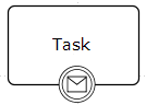
Task (Receive) |
Task receives a message from another pool. The task can have an inbound message flow. |
|
Task (Send) |
Task sends a message to another pool and can be connected to a flow object in another pool through a message flow. |
|
Task (User) |
Task awaits an entry by the user; that is, the user makes a task list entry |
|
Task (Script) |
A task of the script type is executed automatically. |
|
Task (Manual) |
Manual entry of information in the task list |
|
Task (Business Rule) |
Calls up a rule engine. Applies one or more BPM rules. |
|


Sub-Processes
Tasks that can be broken down into smaller components and actually consist of a series of tasks are known as sub- processes. Sub-processes comprise integral detailed processes are divided into three types:
| Type | Use | Icon |
|---|---|---|
Sub-Process |
A sub-process is dependent on a higher-level process and cannot be used independently of that process. A sub-process is used to summarize detail activities. |
|
Event Sub-Process |
An event sub-process is placed in another sub-process. It is triggered by a start event and can interrupt the surrounding sub-process depending on the type of sub-event or can be executed in parallel to it. Refer to Modeling Event Sub-Processes in Business Process Diagrams. |
|


Call Activity
A call activity represents a globally defined sub-process or a globally defined task that is used in the current process, for example,  .
It references either a task that has been defined as global or the start event in a linked process.
.
It references either a task that has been defined as global or the start event in a linked process.
User-Defined Tasks in Business Process Diagrams
You can create your own, user-defined tasks that can be used in profiles and displayed in the INUBIT Workbench.
Refer to Creating User-defined Tasks - BPDs Only.
If you have not yet started the INUBIT Process Engine for the first time, you can adjust the tool_profiles.xml file.
Proceed as follows
Adjust the file <SUITE-INSTALL-DIR>/inubit/server/ibis_root/conf/tool_profiles.xml.
You can use the pattern of the already existing user-defined tasks to create new stereotypes.
Events in Business Process Diagrams
Events occur in the course of a process and influence the process flow. They have either a cause or an effect. There are three types of events:
| Type | Use | Icon | ||
|---|---|---|---|---|
Start events |
Initiate the execution of a process.
|
e.g. |
||
Intermediate events |
Occur between start and end events. They influence the process flow, but do not directly start or end it. |
e.g. |
||
End events |
Display the end of a process |
e.g. |


Sub-Types of Start Events
Some start events can be divided into two event sub-types depending on how they are used in event sub-processes:
-
Event Sub-Process interrupting
A start event of the Event Sub-Process interrupting type interrupts the higher-level process as soon as the event sub- process is started by this start event. You configure this attribute with the Interrupting option in the attribute dialog of the start event that you call via the context menu Edit > Start Event Settings.
-
Event Sub-Process non-interrupting
A start event of the Event Sub-Process non-interrupting type does not interrupt the higher-level process when the event sub-process is started by this start event. You configure this attribute with the Interrupting option in the attribute dialog of the start event that you call via the context menu Edit > Start Event Settings.
Sub-Types of Intermediate Events
For intermediate events, a distinction is made between the following sub-types:
-
Catching
With catching intermediate events, the process is continued after the event occurs.
The symbol in the INUBIT Workbench is unfilled and looks like this:

-
Throwing
With throwing intermediate events, an event is triggered and the process continued.
The symbol in the INUBIT Workbench is filled and looks like this:

-
Boundary
Some intermediate events (cf. BPMN specification 2.0) can be used as intermediate boundary events. They are placed at the boundary of an activity and define that a task or a sub-process will be prematurely terminated if the intermediate event attached to the boundary occurs. If such an event occurs, the outgoing sequence flow does not take its normal course but rather branches to an exception flow connected to the intermediate event.
The INUBIT Workbench supports the correct use of intermediate events attached to the boundary of an activity and only allows intermediate events to be attached to the boundary of tasks and activities and merged with the process if they are permitted by the BPMN specification. This is displayed in the INUBIT Workbench, for example, as follows:
For an example of how an intermediate boundary event is used refer to Defining Transactions and Compensations in Business Process Diagrams.
Intermediate boundary events can be interrupting or non-interrupting:
-
Boundary interrupting
For a boundary and interrupting intermediate event, there is a response to the event and the running activity is terminated. You configure this attribute with the Cancel Activity option in the attribute dialog of the intermediate event that you call via the context menu Edit > Intermediate Event Settings.
-
Boundary non-interrupting
For a boundary and non-interrupting intermediate event, there is a response to the event and the running activity is not terminated. You configure this attribute with the Cancel Activity option in the attribute dialog of the intermediate event that you call via the context menu > Edit > Intermediate Event Settings.
Display of Event Types
In the INUBIT Workbench, the different event types are displayed with several symbols that show the type of event.
Gateways in Business Process Diagrams
You can use elements in the Gateways group to model the branching and merging of process paths. The following gateways exist:
| Type | Use | Icon |
|---|---|---|
Exclusive Gateway (XOR) |
|
|
Event-Based Exclusive (XOR) |
The gateway decides how the sequence flow is divided depending on events that occur. It is always followed by events or recipient tasks. The sequence flow is directed to the event that occurs first. If an incoming signal reaches the gateway, the process is continued. It does not wait for signals from other incoming paths. Additionally, you can define for event- based exclusive Gateways if these should initiate processes. |
|
Inclusive Gateway (OR) |
|
|
Complex Gateway |
|
|
Parallel Gateway (AND) |
|
|


Artifacts in Business Process Diagrams
Artifacts are used to map additional information associated with business processes within a BPD. There are four types of artifacts:
| Type | Use | Icon |
|---|---|---|
Data |
Object Data objects contain information about what activities require for their execution and/or what they generate. Data objects do not directly influence the sequence or message flow of the process. Data objects can be data and information in any form. To show that you are dealing with a set of data objects (e.g. a list with order items), data objects can be visualized as list data objects. |
|
Data Store |
Location at which the process can read or write data, e.g. a database or a filing cabinet. It exists independently of the life span of the process. |
|
Data Input |
Data input is external input for the entire process and specifies which data the process needs as input in order to work. It can be read by an activity. |
|
Data Output |
Data output represents the data that has been generated by the process and returned. |
|
Group |
You can group elements independent of process logic. The grouping of activities is only for the sake of clarity; it does not influence the sequence flow. Groups can also be used to mark the activities of a transaction distributed across multiple pools. |
|
Message |
A message points to the content of communication between two participants. A light letter symbol stands for a message with which an activity is triggered. You configure this attribute with the Throwing option in the attribute dialog of the intermediate event that you call by choosing Edit > Message from the context menu. |
|
Image |
Any graphic in Refer to Using Own Graphics as Symbols. A repository image can be inserted via the context menu of the image symbol. |
|
Text Annotation |
Text annotations contain user-specific texts with explanations and remarks for a particular model element. |
|


Conversation and Choreography in Business Process Diagrams
Within a BPD you use conversations to record the message exchange between process participants in compact form and to describe which communication relationships are involved. You use choreographies to display the partners involved in a business-to-business scenario and the flow sequence of the interaction of the process participants and their message exchange. You can use the following elements to do so:
| Type | Use | Icon |
|---|---|---|
Communication |
Covers the smallest quantity of messages relating to a particular topic. A communication is modeled using two or more conversation links. |
|
Sub-Conversation |
You use sub-conversations to arrange conversations in hierarchies. A sub-conversation is described in more detail in a detailed conversation diagram. |
|
Call Conversation |
A call conversation calls a global conversation or a global communication. |
|
Choreography Task |
A choreography tasks represents an interaction between two process participants, whereby a distinction is made between the initiating and the receiving participant. The participant initiating the conversation is displayed in white; the receiving participant is displayed in gray on the other side. |
|
Choreography Sub-Process |
Choreography sub-processes are used to arrange choreographies in hierarchies. You get additional, detailed choreographies. |
|
Call Choreography Activity |
A call choreography activity calls either a global choreography task hence, one that has been defined once and can be used several times, or a choreography that has been defined elsewhere. |
|


Defining the Execution Behavior of Elements
Overview
You can use various additional attributes that you define for BPD elements to determine their execution response. For example, activities that are repeated several times can be defined as loops or multiple executions. For example, you can configure a process as a transaction with a connected compensation activity if it includes activities that all belong together logically. You can use attributes to define sub-processes as ad-hoc sub-processes, if the order of the included activities is to be determined only at the time of execution.
Defining Loops in Business Process Diagrams
Activities that are executed multiple times can be defined as loops via the settings dialog for the actual element.
| Type | Use | Icon |
|---|---|---|
Standard loop |
This loop activity is continuously executed sequentially as long as the loop condition is true. |
|
Proceed as follows
-
Display the BPD in a local directory.
-
Select the task or sub-process for which you want to make settings.
-
Open the context menu and choose Edit > [Task/Sub-Process] > Settings. A dialog opens.
Configuration options and dialog fields are described in the dialog description Loop, refer to Attribute Dialog: Sub-Process Settings in Business Process Diagrams.
Defining Multiple Executions in Business Process Diagrams
In contrast to a loop activity, the number of required runs is determined in advance for an activity with multiple executions because the number of objects to be processed is known. The individual objects can either be processed sequentially in a particular order or in parallel in any order.
| Type | Use | Icon |
|---|---|---|
Parallel multi-instance marker |
The activity is executed multiple times without a particular order. |
|
Sequential multi-instance marker |
The activity is executed sequentially multiple times, hence, in a particular sequential order, for example, for each individual item of a purchase order. |
|

Proceed as follows
-
Display the BPD in a local directory.
-
Select the task or sub-process for which you want to make settings.
-
Open the context menu and choose Edit > <Task/Sub-Process> Settings. A dialog opens.
-
In the Loop category, choose the Multi-instance loop type. This is how you start the configuration of the multiple executions.
The configuration options for multiple executions are described in the loop type Multi-instance loop in the dialog description Loop.
Defining Transactions and Compensations in Business Process Diagrams
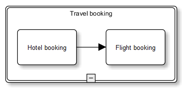
Sub-processes can be defined as transactions. A transaction is a special Sub-Process whose execution can be undone. Associated parts of a process can be combined in a transaction if they constitute a self-contained unit.
A typical example of a transaction Sub-Process is a travel itinerary which is only complete when the processes Hotel booking and Flight booking have been executed successfully. If a part of the transaction process cannot be completed, the entire transaction is deemed unsuccessful. A termination reverses the effects of all activities carried out to that point. This requires the definition of compensation activities.
|
In principle, compensation activities cannot be simulated. |
Several steps are required to define a process as a transaction.
Proceed as follows
-
In the settings dialog of the Sub-Process, choose the attribute Transaction:
-
Display the BPD in a local directory.
-
Select the Sub-Process that you want to configure as a transaction.
-
Open the context menu and choose Edit > Sub-Process settings. A dialog opens.
-
Choose the Sub-Process type Transaction.
Configuration options and dialog fields are described in Transaction.
In the display, the Sub-Process is bordered with a double line as for example:
-
-
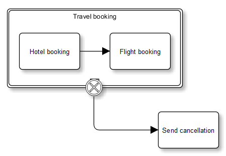
Model a cancel intermediate event attached to the boundary of the activity in the BPD:
When you set the Sub-Process type Transaction, define a cancel intermediate event attached to the boundary of the activity in the BPD as well as a cancellation activity to describe the reaction to a cancellation of the transaction, for example:
Refer to Events in Business Process Diagrams.
-
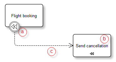
Model a compensation activity in the BPD.
Compensation activities are necessary to undo the effects of activities already carried out, e.g.:
-
Attach a compensation intermediate event to the task that is to be cancelled.
-
Insert a task that serves as a compensation.
-
Connect both modules to a directed association.
The association automatically generates the compensation symbol.
Refer to BPD Modeling Elements.
-
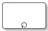
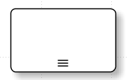
Defining Ad Hoc Sub-Processes in Business Process Diagrams
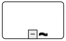
Ad hoc sub-processes only contain tasks. Each task is executed repeatedly until the end condition is fulfilled. The execution sequence is determined dynamically.
A tilde is displayed at the bottom of the Sub-Process symbol:
Proceed as follows
-
Display the BPD in a local directory.
-
Select the Sub-Process that you want to configure.
-
Open the context menu and choose Edit > Sub-Process Settings. A dialog opens.
-
Choose the Sub-Process type AdHoc.
Configuration options and dialog fields are described in section AdHoc, refer to Attribute Dialog: Sub-Process Settings in Business Process Diagrams.
Restructuring and Modularizing BPDs
Overview
The structure of BPDs can be modified and augmented with more detailed information later. You can, for example, insert additional information, replace tasks with a sub-process and increase the diagram’s level of detail for a point in time at which an initial version of the BPD already existed.
Adding Artifacts in Business Process Diagrams
You can store additional information in BPDs in the form of artifacts.
Refer to Artifacts in Business Process Diagrams for a list of all available artifacts.
Changing the Element Type in Business Process Diagrams
You can change elements in diagrams later to achieve a different or more specific display than the original without having to delete and recreate elements. For example, you can change a task into a more specific task.
Proceed as follows
-
Select the element in the BPD that you want to change.
-
Open the context menu and choose Refactoring > Change Type.
-
Select the desired element type from the list.
→ The element is changed into another element of the same element class and the type-specific icon is added to the element symbol.
The refactoring option is context-sensitive and only offers the options that are allowed for the selected BPD element.
Replacing Elements with Sub-Processes in Business Process Diagrams
In the created BPD, you can subsequently summarize tasks to sub-processes and nest sub-processes in other sub-processes. This enables you to create hierarchical process models and structure complex diagrams in clearly arranged modules.
Proceed as follows
-
In the BPD, select the elements that you want to replace with a sub-process.
-
Open the context menu and choose Refactoring.
-
Choose Replace with sub-process.
→ This action generates a new embedded sub-process in the same diagram and places the selected elements in it.
Converting Tasks/Sub-Processes in Business Process Diagrams
Tasks that actually consist of a series of sub-tasks can be displayed later in the BPD as sub-processes; in turn, sub-processes that you later come to regard as atomic tasks can be converted back into tasks.
Proceed as follows
-
Select the element in the BPD that you want to convert.
-
Open the context menu and choose Refactoring > Convert to Sub-Process or Convert to Task.
→ This converts the element into another element class and the corresponding symbol is shown in the display.
|
The refactoring option is context-sensitive and only offers the options that are allowed for the selected BPD element. |
Replacing Elements with a Call Activity in Business Process Diagrams
In a diagram, you can subsequently replace tasks and sub-processes with re-usable process modules (call activities).
The tasks and sub-processes are moved to a different diagram. You can use the corresponding call activities in several higher-level processes and they only have to be implemented once.
Proceed as follows
-
In the BPD, select the element or elements that you want to replace with a call activity.
-
Open the context menu and choose Refactoring.
-
Choose Replace with call activity. A dialog opens.
-
Enter a name for the diagram to be created, choose a diagram group and insert a short description.
-
Enter an e-mail address for the person responsible for the processes of this diagram. He or she is informed through a change notification in case of changes to linked BPDs and TWFs.
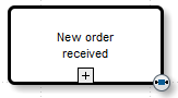
→ The selected elements are moved to a new diagram and replaced with a reusable call activity at the original position. In the new diagram, a new start element is inserted automatically if necessary. A link to this element is generated. The call activity serves as a reference to the moved sub-process. By default, open call activities are shown with a minus sign, closed ones are displayed with a plus sign. At the edge of the call activity, a link symbol appears with which you can branch to the stored activity.
Linking Tasks and Processes in Business Process Diagrams
A central concept in Business Process Diagrams is reusability and linking in modeling. Reusability means that stored and centrally created tasks or entire processes are used several times.
To be able to reuse tasks and processes, you always use a call activity that refers to a globally defined tasks or start event as a reference.
If the call activity is a task, a global task is called. This is created only once and can be called or linked from different processes.
In addition to this, a call activity can call another process. However, only independent processes, not sub-processes, can be linked using call activities.
Linking Global Tasks
If tasks with identical properties are used in different BPDs, the task is created centrally in a diagram only once and defined as globally usable. It can then be used in different processes where it can only be called via a call activity.
Refer to Global Task in section Attribute Dialog: Tasks Settings in Business Process Diagrams.
Prerequisites
-
You have created one or more tasks as globally defined tasks in a separate diagram
-
Diagrams with global tasks have been published
Proceed as follows
-
Display the source diagram in local mode.
-
Drag a call activity to which you want to create a link in the source diagram from the Tools docking window in the sidebar.
-
Open the Links docking window in the sidebar. It shows all available diagrams in the server directory to which you can link the source diagram.
-
Navigate to the target diagram, which contains the task to be linked and drag it to the Call Activity element. A dialog with the target diagram opens and prompts you to click the task to which you want to create a link.
-
Click the task to be linked and click OK.
-
Decide whether you want to adopt the existing name.
-
The task in the source diagram receives a link symbol and is displayed:
Clicking the link symbol takes you to the linked diagram.
Linking Processes
You can use a call activity in a roughly designed BPD to call up another detailed BPD.
Refer to
-
Modularizing Business Process Diagrams: Linking Sub-Processes
-
Deleting a Link: Removing Links
-
Editing a Link: Editing Links.
Linking Processes Distributed across Several BPD Diagrams
For very large and complex processes, it can be necessary to distribute a process model with an associated sequence flow to several diagrams. To do so, you must create a reference from another diagram to show where a certain sequence flow continues. For this case, always use an intermediate result of the Link type.
Proceed as follows
-
Display the source diagram in local mode.
-
At the point in the sequence flow at which the process is supposed to be interrupted, insert a triggering link intermediate event and connect this to the preceding activity, e.g.:
-
Display the target diagram in local mode.
-
At the start of the sequence flow, which is supposed continue the sequence flow interrupted at another point, insert a catching link intermediate event and connect this to the following activity, e.g.:
-
Publish the target diagram.
-
Display the source diagram in local mode again.
-
Open the Links docking window in the sidebar. It shows all available diagrams in the server directory to which you can link the source diagram.
-
Navigate to the target diagram that contains the continuing sequence flow and the catching link intermediate event and drag it to the triggering link intermediate event.
A dialog with the target diagram opens and prompts you to choose the catching link intermediate event.
-
Click the catching link intermediate event and click OK.
-
After the link has been created, the name of the linked link intermediate event (catching) is copied. The triggering link intermediate event in the source diagram receives a link symbol and is displayed, e.g.:
By clicking the link symbol, you go to the continuation of the sequence flow in the linked diagram.
You can also use link intermediate events to refer to different points in the same diagram when it is necessary to interrupt a sequence flow and continue it at another point.
Linking Business Process Diagrams to Reports
You can link sub-processes and tasks in a BPD to reports. For example, you can branch from a support process to a report that lists the duration of the support processing times.
Proceed as follows
-
Display the source diagram in local mode.
-
Open the Report Linking docking window in the sidebar. It lists all reports in the server directory with which you can link the sub-process or the task.
-
Navigate to the desired target report and drag it to the sub-process or task.
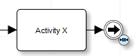
In the sub-process or task, a report link is inserted at the bottom right, e.g.:
-
Publish the BPD. By doing so, you copy the link also into the display of the diagram in the portal’s process viewer.
Double-click the link symbol in the BPD element to open the report.
Returning from the report to the BPD
After you have branched from a BPD to a linked report you can then also return back to your BPD.
Prerequisites
-
In the INUBIT Workbench, you double-click a report link in the BPD to branch to a report on the Reporting tab.
-
The clicked report is selected in the directory tree on the left and displayed on the right.
Proceed as follows
-
Open the context menu of the report selected in the directory tree on the left.
-
Choose Show workflow and navigate to the linked BPD in server or local mode.
By clicking the BPD you return to the Business Process Diagram in the Designer.
Linking Business Process Diagrams to other Diagram Types
You can link Business Process Diagrams to all other diagram types.
For creating and editing links, refer to End-to-end Navigation between Diagrams.
Configuring the Change Notification for Linked BPDs and TWFs
If BPDs are linked to TWFs, you can activate a display that indicates changes to the diagram. As soon as one of the diagrams has been changed, a construction site symbol is displayed on the link.
If it has been configured accordingly, an e-mail notification is also sent to the owner of the linked diagram.
Indicated Changes
Only the following diagram changes are taken into account in monitoring and are indicated as changes:
| Diagram Type | Type of Change |
|---|---|
BPD |
The text for the linked element is changed. |
BPD |
The element linked to the TWF is assigned a different input or output element. |
TWF |
The connection line with the link point is assigned a different source or target module. |
|
If you are only making minimal changes to diagrams, you can suppress the e-mail notification despite the globally set option for change notification for individual cases in the diagram properties when you publish. Refer to Publishing Modules and Diagrams. |
Proceed as follows
Activate the change notification
-
Activate the change notification in the INUBIT Workbench to display a construction site symbol on the link between the linked Business Process Diagram and Technical Workflows as soon as a change is made to the diagram.
Activate e-mail notification
-
To also inform the owner of the diagram by e-mail of the type of change, activate the e-mail notification function globally.
In case of minor changes, the e-mail notification can be suppressed directly in the diagram properties when the diagram is published.
Refer to Publishing Modules and Diagrams.
Define an e-mail address
-
Select the source diagram in the local directory tree.
-
Open the context menu and choose Edit properties.
-
Select the Diagram tab.
-
Enter the e-mail address or the e-mail alias of the person responsible for the diagram in the Responsible (e-mail).
-
Repeat steps 3 - 6 for the target diagram.
Refer to Dialog Description: Diagram Properties.
Create a link
-
Display the BPD that is to be linked to a Technical Workflow in local mode.
-
Open the Links docking window in the sidebar. It shows all available diagrams in the server directory to which you can link the source diagram.
-
Navigate to the Technical Workflow to which the link is to be created and drag & drop it to an element in the BPD. A dialog opens and prompts you to select one or more connection lines that are supposed to be monitored for changes.
-
Follow the dialog instructions and enter the link point(s) in the target diagram.
-
Click OK. In the source diagram, a link symbol is displayed on the linked element.
-
Publish the diagram.
As soon as changes are made to the diagram and the diagram is then published, a construction site symbol on the connection line in the target diagram that was defined for monitoring indicates the change made to the source diagram. Only certain changes are indicated.
Displaying Change Information for Linked BPDs and TWFs
The context menu on the construction site symbol lets you display the changes to linked diagrams.
Displaying the Change Type in Business Process Diagrams
When called up, the context menu of the construction site symbol lists the changes made.
Proceed as follows
-
Display the diagram with the construction site symbol.
-
Open the context menu of the construction site symbol. A list of all changes made in the linked diagram is displayed, e.g. Element name changed.
You can display additional change details for each change
Displaying Differences between BPDs Graphically
You can use a diagram comparison to graphically display the differences before and after the diagram change.
Proceed as follows
-
Display the diagram with the construction site symbol.
-
Open the context menu of the construction site symbol.
-
Choose a change from the list of displayed changes and choose Compare.
→ A window opens showing the differences between the diagram before and after the change.
Displaying the BPD Change Log
You can display diagram changes in a short log.
Proceed as follows
-
Display the diagram with the construction site symbol.
-
Open the context menu of the construction site symbol.
-
Choose a change from the list of displayed changes and choose Change information.
→ A window with the change log opens displaying the details of the diagram change.
Marking Changes as Edited
You can rework the displayed changes and then mark the changes as edited, either all of them at the same time or individually in sequence. This is how you remove the construction site symbol from the respective diagram.
Proceed as follows
-
Display the diagram with the construction site symbol in local mode.
-
Open the context menu of the construction site symbol.
-
Decide whether you want to mark all changes together as edited or each change separately.
-
Mark all changes together:
-
In the context menu, choose Mark as edited.
-
-
Mark each change separately:
-
Choose a change from the list of displayed changes.
-
Choose Mark as edited.
→ The changes are thus accepted as edited and the construction site symbol is removed from the diagram to signalize that there are no inconsistencies between the linked diagrams.
-
-
Modeling Event Sub-Processes in Business Process Diagrams
An event sub-process is an optional part of sub-processes and is used for processing events that occur within the sub-event. In contrast to a normal sub-process, it has neither inbound nor outbound sequence flow because it is not triggered by a sequence flow but by the occurrence of an event during process execution. A distinction is made between interrupting and non-interrupting event sub-processes, depending on the chosen start event. Event sub-processes can only be triggered whilst the surrounding sub-process is active.
To model a sub-process with an enclosed event sub-process, several steps are required, which are illustrated using the simple example of a dinner invitation.
Proceed as follows
-
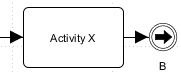
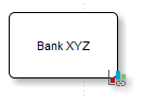
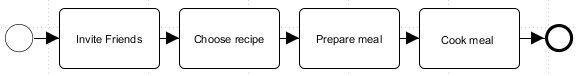
Create a simple process with individual tasks as well as a start and end event, e.g.:
-
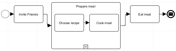
Summarize the two tasks Choose recipe and Cook food to the sub-process Prepare dinner, e.g.:
-
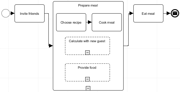
Insert two event sub-processes into the higher-level sub-process Prepare dinner. These event sub-processes are supposed to affect the surrounding sub-processes. Call one event sub-process Plan for new guest and the other Buy food, e.g.:
-
The event sub-process Plan for new guest should be handled in such a way that the surrounding sub-process is not interrupted because of the event. To do so, enter a non-interrupting message start event and another task in the event sub-process.
-
The event sub-process Buy food is to be handled so that the surrounding sub-process is interrupted by it. To do so, insert an interrupting error start event and another task into the second event sub-process, e.g.:
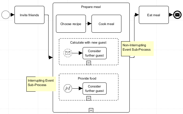
→ Once the event sub-processes have been processed, the surrounding sub-process is left via the regular exit.
Using BPD Templates
Overview
You can make available parts of an existing BPD as a new diagram template and enter created BPD templates in new diagrams.
Creating BPD Templates
Proceed as follows
-
Show the BPD that is to be used as the basis for a new template in the local directory.
-
Within the existing BPD, select all elements that are supposed to be included in the diagram template.
-
Open the context menu and choose Create diagram template. An editor for creating the template opens.
-
Give the template a name and add a short description. This is displayed as a tooltip for every template available in the sidebar.
-
Choose a target directory in the Repository. You store the template at the top level in Global or in a user group, group or higher-level group.
-
In the target directory, you can also create a business-related sub-directory for the template. If necessary, choose a sub-directory or enter the name for a new sub-directory.
-
Enter a file name or copy the suggested file name with the file extension
*.template.→ The newly created template is stored in the Repository in the selected target directory. If you have entered Global as the target directory, the files are located in the folder Diagram Templates > BPD.
Inserting BPD Templates
Proceed as follows
-
In local mode, display the Business Process Diagram that you would like to insert into a BPD template.
-
In the sidebar, open the Templates docking window.
-
Select the target directory (Global, User, Group) and the sub-directory (if necessary) of the templates to be displayed.
-
It displays all available BPD templates with names and previews for each directory and sub-directory. The tooltip shows the description of the template.
-
Drag and drop the desired template from the sidebar to the target diagram.
|
You can update an existing template by inserting it into a Business Process Diagram, changing it and storing it again with the same name. Refer to Editing BPD Templates. |
Editing BPD Templates
Proceed as follows
-
In local mode, create a new Business Process Diagram or open an existing one.
-
Open the Templates docking window from the sidebar.
-
Select the target directory (Global, User, Group) and the sub-directory (if necessary) of the templates to be displayed.
-
Drag and drop the desired template from the sidebar to the target diagram.
-
Change the diagram elements which should be part of the new template version.
-
Select all elements the template should contain after the changing.
-
Right-click one of the selected elements and choose Create diagram template.
-
For the new template use the name, the target directory, the sub directory, and the file name of the original template.
-
Enter a new description if necessary and finally click on OK.
-
Confirm by clicking on OK that you want to update the existing template.
→ The changed diagram will be saved as a new file version in the Repository.
|
You can restore an earlier version of a template in the Repository. In this case it will be added as a new version, it will get a comment, and it will be displayed in the Templates docking window immediately. |
Deleting BPD Templates
The BPD templates created in the BPD Designer can only be deleted again in the corresponding directory in the Repository.
Proceed as follows
-
Display the Repository.
-
In the directory tree, choose the template file to be deleted in the corresponding target directory in folder Diagram Templates > BPD.
The Diagram Templates folder is only displayed in Repository view All.
Refer to View (DropDown list)
-
Open the context menu of the file and choose Delete.
-
Confirm the prompt that appears by choosing Yes.
→ The file is deleted from the Repository and from the view in the templates docking window of the BPD Designer.
|
Deleted files are moved into an attic directory first. To delete files permanently, delete the attic directory via the context menu. To restore files, drag them from the attic directory back into the directory tree. |
ARIS Model Import - Mapping Table eEPC/BPD
Overview
The following applies to the import of ARIS model groups:
-
Only those models are imported that are contained directly in the group. Any sub-groups present in subdirectories are ignored when importing.
-
If an ARIS eEPK model has connections to one or more other models, these connections are retained when importing and the connected models are also imported.
The following table shows how eEPC models are mapped to elements in Business Process Diagrams:
| eEPK | Meaning | BPD |
|---|---|---|
|
Start Event |
|
|
Intermediate Event |
|
|
End Event |
|
|
Task |
|
|
Call Activity |
|
|
Task (Service) |
|
|
Data-based Exclusive Gateway (XOR) |
|
|
Parallel Gateway (AND) |
|
|
Inclusive Gateway (OR) |
|
|
Artifact Image |
|
|
Pool with Lanes |
|


Dialog Descriptions in Business Process Diagrams
Attribute Dialog: Tasks Settings in Business Process Diagrams
In this dialog, you configure the settings for loops.
|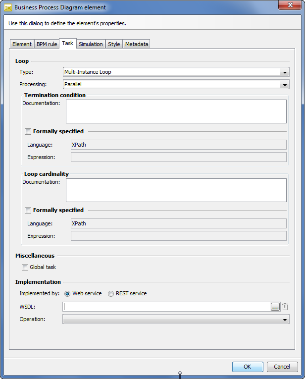
Loop
-
Type
For defining the loop type.
-
Processing (for loop type = Multi-Instance Loop)
For defining whether the activity for the individual elements is executed sequentially or in parallel.
-
Test time (for loop type = default loop)
Indicates whether the loop condition is checked before or after executing the activity. If the value is set to after (Until), the activity is executed at least once even if the loop condition is not true at the start.
Loop condition
-
Documentation (for loop type = default loop)
Describe the condition as free text. The loop is processed as long as the loop condition is true. The loop is terminated only when it is no longer true.
Termination condition
-
Documentation (for loop type = Multi-Instance loop)
Free text describing how often the loop is executed until it terminates.
Formally specified
With this option you can also define the termination condition as formal, hence, executable.
-
Language
Should always be XPath.
-
Expression
Define the termination condition as an XPath. Clicking the button opens the XPath Wizard.
Refer to XPath Assistant.
Loop cardinality
-
Documentation
Define a numeric expression ([0…1]) that specifies the number of created instances.
Formally specified
With this option you can also define the loop cardinality as formal, hence, executable.
-
Language
Should always be XPath.
-
Expression
Define the loop condition as an XPath. Clicking the button opens the XPath Wizard.
Refer to XPath Assistant.
Miscellaneous
-
Global Task
Select this option if you want to release the created task for reuse in other processes. It can then be integrated and called in various other processes with a call activity.
Implemented by
-
Web service
-
WSDL (only for tasks of types Send, Receive, and Service)
Specify a WSDL file to store a Web Service. In order to link the task with a WSDL file, enter the URL of the WSDL file or select a WSDL from the Repository.
-
Operation (only for tasks of types Send, Receive, and Service)
Specify an operation of a Web Service.
-
-
REST Service
-
Resource URI
Specifiy the URI of a REST Connector or select a REST Connector using the
 icon.
icon. -
Method
Specifiy the method of the REST Connector.
-
-
Task Generator (only for tasks of the User type)
Choose a task generator to generate an entry for the user task in the task list
-
Workflow to be executed (only for tasks of the Script type)
Choose a workflow. A Technical Workflow is used to define a script for a script task.
-
VR Connector (only for tasks of the BPM Rule type)
Select the VR Execution Connector that will be used for the task. As a rule, only one VR Execution Connector can be assigned to one task. After selection, the list containing the services provided by the connector is filled in. Thus, a service can be selected and further details such as service version and the actual rule can be defined.
-
Rule Service (not editable)
Name of the rule service
-
Version (not editable)
Version of the rule service
-
Rule (not editable)
Name of the rule
-
Description (not editable)
Description of the rule
-
Attribute Dialog: Call Activity Settings in Business Process Diagrams
Call up
Call Activity > Context Menu > Edit > Call Activity Settings tab
Miscellaneous
Execute sub process by using the role of the actual lane: When activated, the role of the current lane is passed to the sub process. Otherwise, the role defined for the sub process is used.
Attribute Dialog: Sub-Process Settings in Business Process Diagrams
Call up
Sub-Process element > Context Menu > Edit > Sub-Process Settings tab
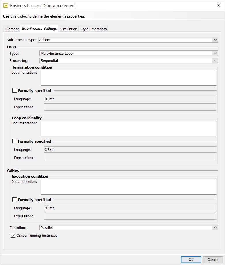
In this dialog, you configure the settings for loops, transactions and ad hoc Sub-Processes.
Sub-Process Type
Choose whether your sub-process is supposed to be configured as a normal sub-process, ad-hoc or transaction sub- process.
Refer to
Loop
-
Type
For defining the loop type:
-
Test time (for loop type = default loop)
Indicates whether the loop condition is checked before or after executing the activity. If the value is set to after (Until), the activity is executed at least once even if the loop condition is not true at the start.
-
Processing (for loop type = Multi-Instance loop)
Indicates whether the activity is executed in parallel or sequentially for the individual elements
Loop condition (for loop type = default loop)
-
Documentation
Formulate the condition as free text. The loop is processed as long as the loop condition is true. The loop is terminated only when it is no longer true.
-
Formally specified
With this option you can also define the loop condition as formal, hence, executable.
-
Language: Should always be XPath.
-
Expression: Define the loop condition as an XPath. Clicking the button opens the XPath Wizard.
Refer to XPath Assistant.
-
Number of loops (for loop type = default loop)
Defines how often the loop is executed at maximum.
Termination condition (for loop type = Multi-Instance loop)
-
Documentation
Free text describing how often the loop is executed until it terminates.
-
Formally specified
With this option you can also define the termination condition as formal, hence, executable.
-
Language: XPath.
-
Expression: Define the termination condition as an XPath. Clicking the button opens the XPath Wizard.
Refer to XPath Assistant.
-
Loop cardinality (for loop type = Multi-Instance loop)
-
Documentation
Define a numeric expression ([0…1]) that specifies the number of created instances.
-
Formally specified
With this option you can also define the loop cardinality as formal, hence, executable.
-
Language: Should always be XPath.
-
Expression: Define the loop condition as an XPath. Clicking the button opens the XPath Wizard.
Refer to XPath Assistant.
-
Transaction
(Only for sub-process type = Transaction)
-
Log
Entry of a transaction log (for example, two-phase commit) as free text that describes the transaction behavior of the sub-process.
-
Method
Select a method from the list for monitoring and reversal of the transaction following termination. The standard method as per the BPMN specification is Compensate.
AdHoc
(Only for sub-process type = AdHoc)
-
Completion condition
In the Documentation field, you define the condition indicating when the ad hoc process is completed using user- defined text.
-
Formally specified
With this option you can also define the completion condition as formal, hence, executable.
-
Language: XPath
-
Expression: Define the completion condition as an XPath. Clicking the button opens the XPath Wizard.
Refer to XPath Assistant.
-
-
Execution
Indicates whether the tasks within the ad-hoc sub-process are executed in parallel (default value) or sequentially.
-
Cancel running instances
If you have chosen parallel execution, you can use this option to specify whether the running instances are terminated when the completion condition occurs.
Attribute Dialog: BPM Rule in Business Process Diagrams
Call up
Task (Business Rule) > Context Menu > Edit > BPM Rule
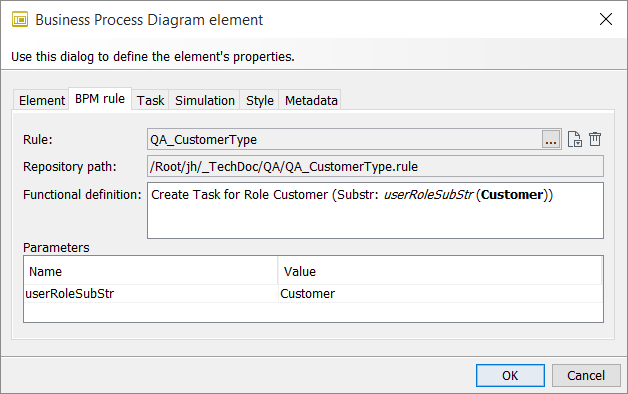
You can define BPM rules for tasks, which are then used for task assignment and delegation.
-
Rule
Click the
 icon to navigate to a rule in the Repository and select it.
-
Create new rule
Click the
 icon to create a new rule in the Repository.
 -
Delete rule
Click the
 icon to remove the rule.
-
The other fields are taken over from the rule definition and cannot be changed.
Refer to
Attribute Dialog: Choreography Task, Choreography Sub-Process, Call Choreography Activity in Business
Process Diagrams
Call up
Choreography element > Context Menu > Edit > Choreography <Element>
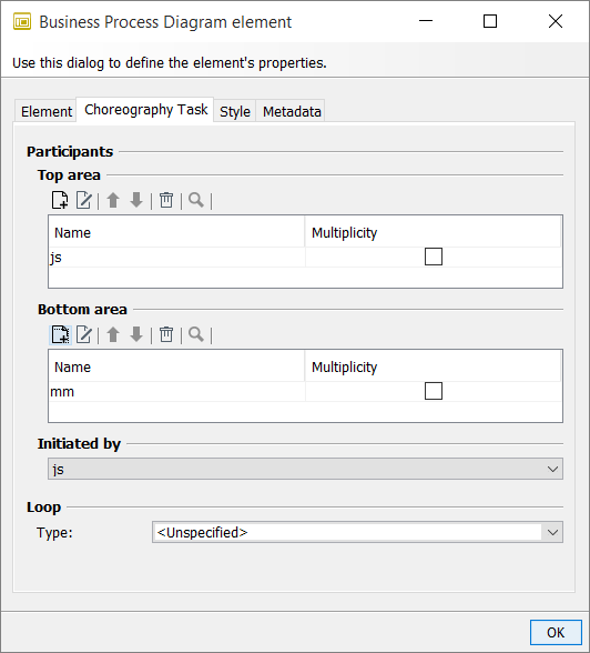
In the attribute dialog, you configure the participants and the interaction sequence for the message exchange in a choreography diagram.
Participants
-
Top area/Bottom area
Specify the communication partners and, if necessary, add a multiplicity in case of groups of parties involved in the process.
-
Initiated by
Define which participant starts the message exchange. The initiating participant turns graphically white, the receiving participant is highlighted in gray.
Loop
Type
In addition, you can execute a choreography task as a loop.
To configure a loop refer to Attribute Dialog: Sub-Process Settings in Business Process Diagrams.
Attribute Dialog: Data Object/Data Input/Data Output in Business Process Diagrams
Call up
Data Object/Data Input/Data Output > Context Menu > Edit > Data Object/Data Input/Data Output
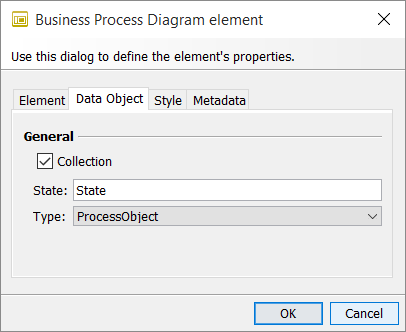
In the attribute dialog for data object, data input and data output, you define whether artifacts are list elements or multiple elements.
General
-
Collection
Select this option if you want to specify that you are not dealing with an individual data record but a set or list of data records. Graphically, the icon is displayed with three lines to indicate that it is a list object or list input data/output data.
-
Status
Here, you can enter a user-defined text to store status information for artifacts, which is displayed under the icon in the diagram.
-
Type
Type of the data object
Attribute Dialog: Data Store in Business Process Diagrams
Call up
Data Store > Context Menu > Edit > Data Store
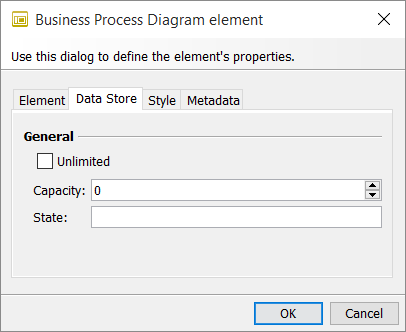
In the attribute dialog for the data store, you can enter a certain capacity or an unlimited availability of the data store.
General
-
Unlimited
Select this option if the data store is supposed to be available with unlimited capacity.
-
Capacity
Specify the capacity of the data store here.
-
Status
Here, you can enter a user-defined text to store status information for the data store, which is displayed under the icon in the diagram.
Attribute Dialog: Gateway Settings - Event-based Gateway - in Business Process Diagrams
Call up
Gateway > Context Menu > Edit > Gateway Settings
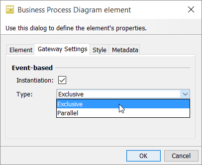
In the attribute dialog for event-based gateways, you specify that these are supposed to start (instantiate) a process. You use this to define the gateway type Exclusive event-based gateway and Parallel event-based gateway.
Event-based
-
Instantiation
Activate this option if you want to use the event-based gateway as an initial element in a process.
-
Type
-
Exclusive
The process is started as soon as one of the following events occurs.
-
Parallel
The process is started only when all the following events occur.
-
Attribute Dialog: Gateway Settings - exclusive Gateway - in Business Process Diagrams
Call up
Gateway > Context Menu > Edit > Gateway Settings
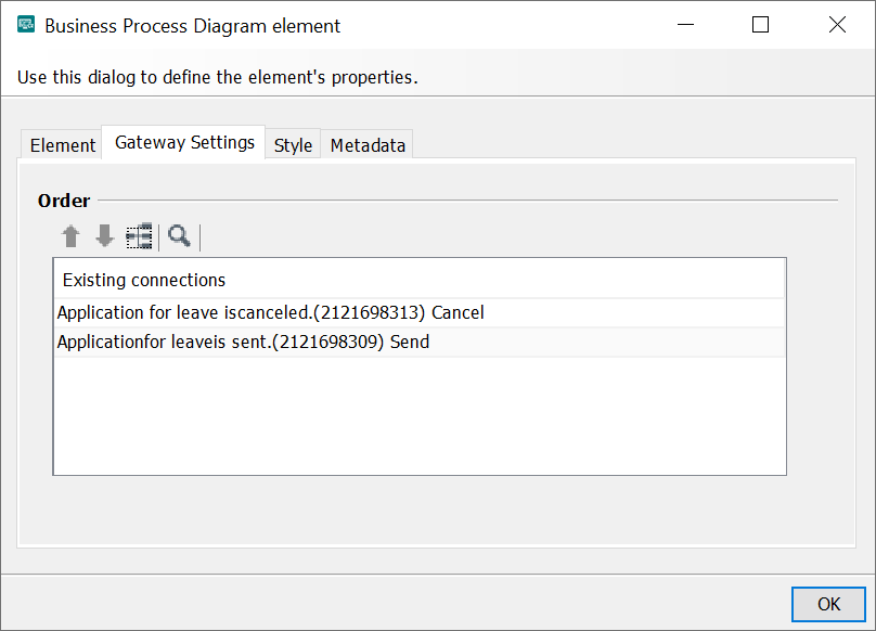
In the attribute dialog for exclusive gateways, you specify the order in which the single sequence flows are to be processed.
In the connection list, the following information appear:
<target name>(<target ID>) <name of the connection to the target>
Attribute Dialog: Message in Business Process Diagrams
Call up
Message Element > Context Menu > Edit > Message
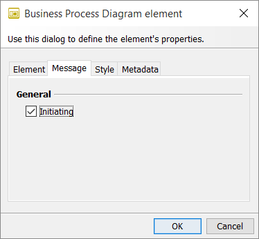
In the attribute dialog for message artifacts, you define whether messages between communication participants trigger an activity.
General
Initiating
If selected, the corresponding message triggers an activity. The message symbol is displayed in white.
If this checkbox is not selected, the system displays a gray envelope symbol for received messages.
Attribute Dialog: Pool in Business Process Diagrams
Call up
Pool Element > Context Menu > Edit > Pool
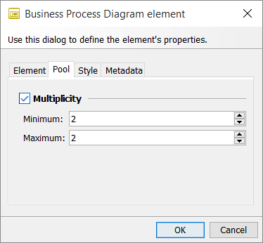
In the attribute dialog for pools you define whether the process participant displayed as a pool represents a group of participants.
Multiplicity
Select this option if you want to display the pool as multiple participants in the process. You thus define that the pool represents a group of participants.
-
Minimum/Maximum
Enter a minimum value and a maximum value for it. Graphically, the icon is displayed with three lines indicating multiple participants/a multi-instance pool.
Attribute Dialog: Start Event in Business Process Diagrams
Call up
Context Menu > Edit > Start Event settings
Mode: Standard, Executable
In the attribute dialog for start events, you configure whether a start event interrupts an event sub-process.
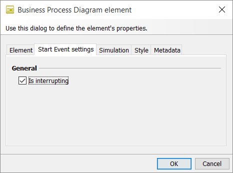
General
Interrupting
-
If this is selected, the higher-level sub-process is terminated as soon as the event sub-process is started by this start event.
-
If this is not selected, the higher-level process is not interrupted by the start of the event sub-process.
Refer to Sub-Types of Start Events
Attribute Dialog: Intermediate Event in Business Process Diagrams
Call up
Context Menu > Edit > Intermediate Event Settings
Mode: Standard, Executable
In the attribute dialog for intermediate events you configure whether an intermediate boundary event is supposed to interrupt an activity.
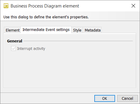
General
Cancel activity
If this is selected, the system responds to the intermediate event and the current activity is terminated.
Refer to Sub-Types of Intermediate Events