Integrating Systems and Automating Processes
|
There are example diagrams for all tutorials in the INUBIT software |
Prerequisites
-
You have installed the INUBIT Process Engine & Workbench set.
-
You have added a valid license.
-
You have logged in to the INUBIT Workbench with the user miller in order to access to the example diagrams
Enterprise Application Integration
The INUBIT software enables the automation of business processes, incorporating internal IT systems, employees, external customers, and partners. Numerous standard modules and support for a large number of communication protocols enable the direct integration of systems such as SAP and databases.
The individual modules are assembled into Technical Workflows in a workflow designer using Drag’n’Drop. Error branches, alternative connectors, and error scopes enable error situations to be handled easily; functions range from notification via e-mail, SMS, or SNMP to complex error workflows. The Technical Workflows can be closely linked with the business process diagrams.
Converting data
The handling of data in Technical Workflows is universally based on XML. Format adapters convert non-XML to XML and vice versa. In-house formats can be freely defined in a flat file adapter and used. The data structures are depicted in a converter using Drag’n’Drop. This converter returns standard-compliant XSLT. The XSLT converter provides an integrated test environment along with checks against schemas and DTDs.
Navigation and debugging
You can navigate in a top-down way from the technical business process to the technical implementation in a Technical Workflow to classify errors that occur during routine operation. The integrated test environment enables the convenient debugging of the Technical Workflows; the transfer of workflows from the development to the production system is supported by the integrated deployment process. Running workflows can be monitored in real time in watch mode.
Application Example
A Technical Workflow is the technical implementation of a business process. It contains one or more modules that fetch messages from a source system or receive messages from a source system, convert and modify them, and then pass them to a subsequent target system.
The system connectors are responsible for communication between the source and target systems and the INUBIT software. Numerous adapters and converters are available for converting and modifying messages.
The order in which the modules are executed is defined by the workflow control. The workflow control also defines the conditions under which a module is executed and how often it is executed. The execution of a workflow does not have to be linear - branches and loops are possible.
In addition to simple 1:1 transformations that convert an input message to an output message, the use of workflow controls such as multiplexers and demultiplexers also enables N:M transformations.
Example
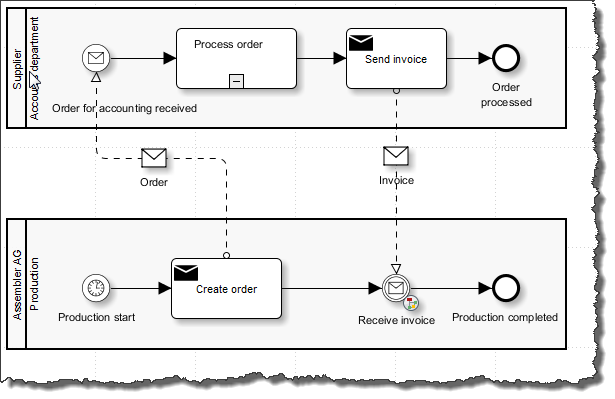
The depicted Technical Workflow - Order Supplier A - sends an order from Assembler AG to supplier A. The supplier requires the order as a CSV file that can be processed in its warehouse management system. Both business partners exchange data via FTP.
Assembler AG issues the order in openTRANS format in their ERP system. The ERP system is connected to the INUBIT software. The order is first converted to a CSV-XML format in the workflow. It is then converted to CSV and sent to the supplier by FTP.
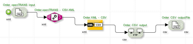
The Technical Workflow consists of the following modules (from left to right):
-
File Connector Order openTRANS input
This system connector loads the order to be processed from the Assembler AG file system.
-
XSLT Converter Order openTRANS - CSV-XML
This converter converts the order from one XML format into another XML format.
-
XML-CSV Adapter Order XML - CSV
This format adapter transforms the data from XML format to CSV format.
-
FTP Connector Order CSV output
This system connector transfers the data to the FTP server of Supplier A.
-
File Connector Order CSV outputFile
This connector serves as an alternative connector. It is used if e.g. the FTP server is not available. The file is then stored in the Assembler AG file system.
|
The depicted Technical Workflow serves only as an example and is not included in the tutorial as executable Technical Workflow! |
Creating a Technical Workflow 1: Reading a File from the File System
Assembler AG receives invoices from the supplier in CSV format but requires invoices in openTRANS format.
A Technical Workflow therefore fetches all invoices from the file system using a File Connector. The workflow then converts them from CSV-XML format to CSV format and then from CSV format to openTRANS format.
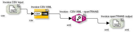
Your task is to recreate the depicted workflow in a functional way.
Creating a Diagram
Proceed as follows
-
Create an empty Technical Workflow diagram:
-
On the Designer tab, display the local directory.
-
Select the Technical Workflows folder and open the context menu.
-
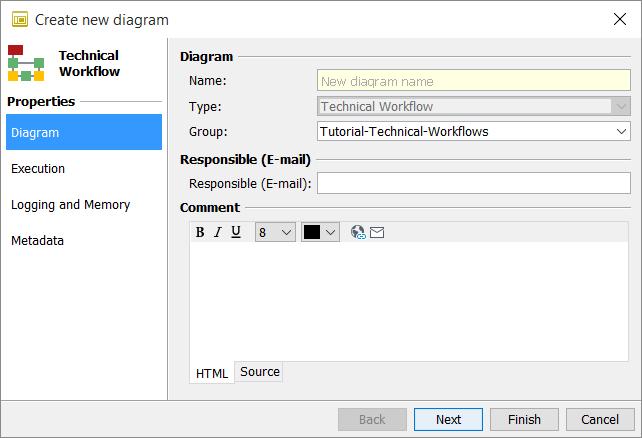
Select New from the context menu. The diagram wizard opens:
-
-
Specify the properties of the new workflow diagram here:
-
Call the workflow 1_Invoice Supplier A.
-
Enter 1_Supplier A Workflows as the workflow group.
Leave the other settings as they are.
-
-
Click Next. The page Execution is displayed.
-
In the Workflow status area select the checkbox Active.
-
Click Next, until the page Metadata is displayed. There is no need to change any settings on these pages.
-
Click Finish.
→ The wizard closes and the workflow is generated in your local directory.
Creating Modules
Proceed as follows
-
To the right of the workspace in the sidebar, click Tools. The docking window Tools opens.
-
Click the System Connector group and drag a File Connector onto the diagram’s workspace.
A wizard opens to guide you through the module configuration steps. Make entries for the following fields in the first dialog:
-
Name: 1_invoice CSV input
-
Input: csv
-
Output: csv
-
-
Click Next.
The Input Connector option is already preselected correctly, since the File Connector should actively fetch data from the directory.
The status can remain as inactive as long as the workflow is started manually rather than being scheduled. Ignore all further fields in this dialog.
-
Click Next. You can ignore the Scheduler dialog for the time being.
-
Click Next.
-
Make sure, the File mode option is selected.
-
Enter
<SUITE-INSTALL-DIR>/inubit/client/tutorial/miller(absolute path) as the directory andInvoice.csvas the file name. -
De-select the option Delete files after reading. If this option is selected, you can only test this module once, because after the first test the test file is missing.
-
-
Click Finish.
→ The wizard closes and the configured File Connector is displayed in the workspace.
Testing the Workflow
All workflows with at least one module can be tested.
Refer to Test Mode: Testing Diagrams
Executing the Test
Proceed as follows
-
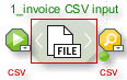
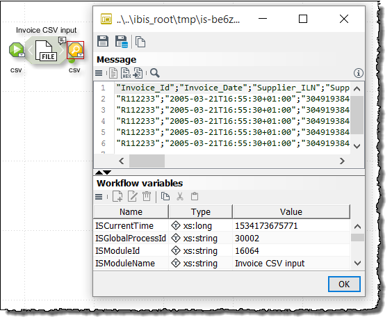
Open the context menu of the Invoice CSV input File Connector and select Set start point. A green start point is displayed.
-
Click in the workspace and select Start test without file from the context menu.
The test starts. The test file is found and read using the path specification defined in the File Connector. A small green dot moves through the workflow and displays the current processing state.
After the test a yellow dot is displayed to the right of the connector, this is a so called watch point. You can display the current interim result of message processing at each watch point.
Once the workflow has successfully run, a corresponding message appears. If an error occurs, the processing of the workflow stops and a red highlighting is displayed along with an error message.
Creating a Technical Workflow 2: Converting a CSV File to CSV-XML
This section explains how to convert the CSV file into an interim XML format using the CSV-XML adapter. This interim format is required to enable the generation of the openTRANS format in the next step; openTRANS format is required by the Assembler AG’s ERP system.
Proceed as follows
-
In the sidebar click Tools and open the Format Adapter folder.
-
Drag a CSV-XML Adapter onto the workspace.
The module wizard opens.
-
Fill in the fields as follows:
-
Name: 1_Invoice CSV-XML
-
Input: csv
-
Output: xml
-
-
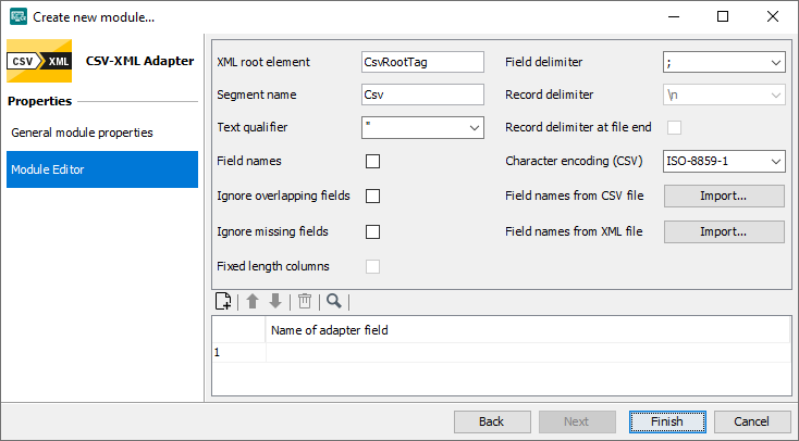
Click Next. The Module Editor page is displayed:
Change the following entries:
-
XML Root Element field:
Name of the root node in the XML file to be generated. Enter Invoice.
-
Segment name field:
Name of the child element (here: the invoice item). Enter Item.
-
-
Select the Field names checkbox.
-
Next to Field names from CSV file, click the Import button to load the file from which the CSV field names are to be read. A file explorer dialog opens.
-
Navigate to the
<SUITE-INSTALL-DIR>/inubit/client/tutorial/miller/Invoice.csvCSV file and load it. A prompt appears. Confirm the prompt by clicking Yes. The field names are adopted from the CSV file in the order in which they occur and then displayed. When the adapter is executed, an XML element is generated from each field name. Now, the configuration of the CSV-XML Adapter is complete. -
Click Finish. The module wizard closes. The CSV-XML Adapter icon is displayed on the workspace.
-
Connect the File Connector with the CSV-XML Adapter.
|
Test both modules again and display the generated interim XML format. |
Creating a Technical Workflow 3: Converting CSV-XML to openTRANS
This section explains how to convert the interim XML format to openTRANS format using an XSLT converter.
The XSLT converter provides a graphical interface that you can use to easily create an XSLT style sheet via Drag’n’Drop. The XSLT style sheet is used to convert the XML input message to the openTRANS output message (which is also XML- based).
Refer to XSLT Converter
Creating the XSLT Converter
Proceed as follows
-
In the sidebar click Tools and open the Data Converter folder.
-
Drag the XSLT Converter onto the workspace.
The module wizard opens.
-
Fill in the following fields:
-
Name: 1_Invoice - CSV-XML - openTRANS
-
Input: xml
-
Output: xml
-
-
Click Next. The next page is displayed. There is no need to change any settings on this page.
-
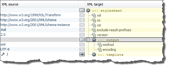
Click Next. The Module Editor tab is displayed:
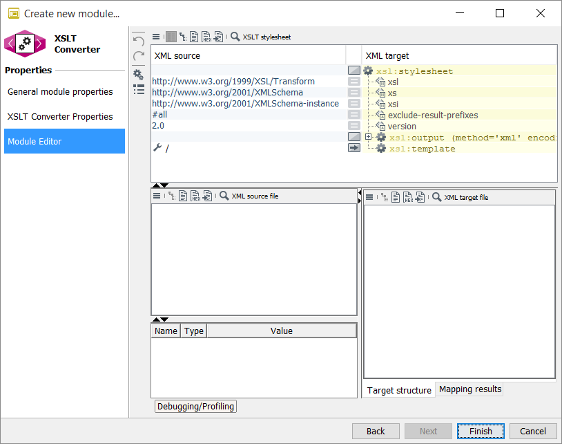
The XSLT Converter has a three-part interface:
-
Top: Displays the style sheet
-
Bottom left: Displays the source message and values
-
Bottom right: Displays the target message
The source and target message serve as templates for the structure of the output message. The XSLT style sheet is applied to the XML input message and generates the XML output message in accordance with the structure of the XML target message.
-
Specifying the Input and Target Message
Proceed as follows
-
Click the
 button at the bottom left and select Open > File.
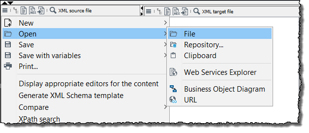
Navigate to the message
CSV-XML_Invoice.xmlfile and load it. You find the message in the<SUITE-INSTALL-DIR>/inubit/client/tutorial/miller/directory.You can create the required input message yourself by testing the workflow (File Connector and CSV- XML Converter) and saving the result file from the last watch point on your PC.
-
Proceed in the same way to load the
openTrans_Invoice.xmltarget file at the bottom right. This file is located in the same directory.Once the file has been opened, the relevant XML root nodes are displayed. To view the entire structure of the source and target file, select Expand all from the context menu of the root node in question.
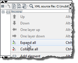
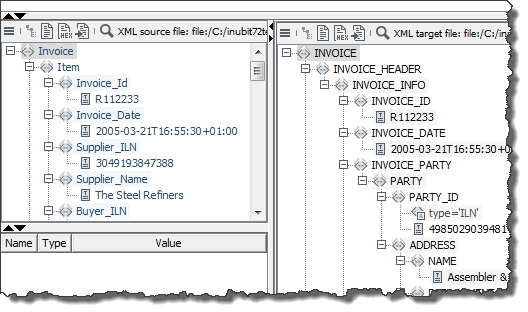
Once you have expanded both XML files, you can see that the target file in openTRANS format has a more nested, significantly more complex structure than the input message:
-
Source message (left):
In the CSV-SML file, an invoice item is represented by
<Item>. Data is assigned within a line on the basis of the items, which are separated using semicolons. The data is represented by the XML elements displayed below<Item>.Each
<Item>element has the same children (the elements<Invoice_Id>to<Tax>. This means that each<Item>contains the same basic information. A large proportion of this data is therefore redundant. -
Target message (right):
The top level is broken down into
<INVOICE_HEADER>,<INVOICE_ITEM_LIST>, and<INVOICE_SUMMARY>.<INVOICE_ITEM_LIST>contains multiple<INVOICE_ITEM>(the individual items to be placed into the invoice). The<INVOICE_HEADER>element contains the basic invoice information, which, in openTRANS, appears only once and not for every invoice item.Now map the elements from the input message to the elements in the target file. In the case of the two files in the example, you can easily find certain correlations between the source and target file thanks to the similar element names, e.g.:
Element in input message Element in target file Invoice_IdINVOICE_IDInvoice_DateINVOICE_DATEPosition_IdLINE_ITEM_IDCurrencyPRICE_CURRENCYItemINVOICE_ITEM
-
Preparing the Target File
Proceed as follows
-
Only the structures are important in the target file, not the data contained therein. You can therefore click the
button in the XML target file area and select Remove data from structure to gain a better overview of the file. -
The target file contains multiple
<INVOICE_ITEM>elements. However, the number of invoice items in the output message should dynamically change to the number of items in the input message. You therefore only require a single<INVOICE_ITEM>element to serve as a structural template. Click the button again and activate the Only distinct nodes option.
Mapping the Target Structure
The basic structure of the XSLT style sheet is already specified in the upper area:
Proceed as follows
-
First, define which elements are to be generated. To do so, drag the
<INVOICE>element from the XML target file area up to the yellow XML target area and drop it onto thexsl:templateelement.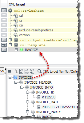
-
Expand the
<INVOICE>element in the style sheet. You can now see that the element with all its child elements has been appended to thexsl:templateelement: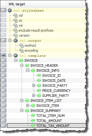
→ Now you have defined the openTRANS structure in the XSLT style sheet.
Mapping the Input Message Elements to the Target Structure
Proceed as follows
-
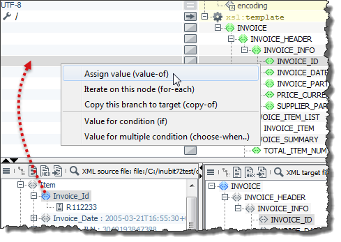
Start with the basic invoice information. Drag the
<Invoice_ID>element from the XML source file area up to the XML source area. Drop the element onto the<INVOICE_ID>line.The following menu opens:
-
Select Assign value (value-of). The result looks like this:
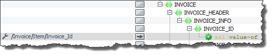
You use the
xsl:value-ofcommand to define that the content of the target element should be the same as the content of the source document. -
The
Invoice/Item//Invoice_Idelement appears several times in the input message. To select only theInvoice_Idof the firstItemelement you must modify the XPath syntax to look like this: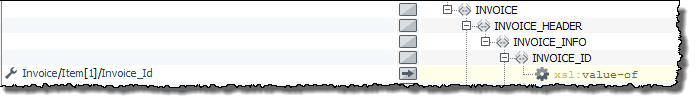
You can test each work step by clicking the
 button in the toolbar.
The XSLT processor then generates an output message that appears at the bottom right on the Mapping results tab.
You will notice that a test with the current XSLT style sheet for the
button in the toolbar.
The XSLT processor then generates an output message that appears at the bottom right on the Mapping results tab.
You will notice that a test with the current XSLT style sheet for the <INVOICE_ID>element returns the valueR112233as expected. -
Proceed in the same way for subsequent elements up to and including
<Currency>: Find the correlations between XML source and XML target and map them using the Assign value (value-of) function. Afterwards, define that only* the firstItemelement should be used.
Creating a Loop
The nodes from <Position_Id> to <Tax> contain data that is different for each <Item> element.
In addition, each invoice may have more than one article (here: 5 <Item> elements).
It therefore makes sense to use a loop to map recurring child elements with different elements.
Proceed as follows
-
Drag a
<Item>element from the XML source file area and drop it onto the<INVOICE_ITEM>line (below<INVOICE_ITEM_LIST>). The selection menu opens. -
Select Iterate on this node (for-each). This defines that all statements below this command are to be repeated. An
<INVOICE_ITEM>element is therefore created for each Item element in the input message, including all child elementsTest the XSLT style sheet to reproduce the loop effect.
-
Map the elements from
<Position_Id>to<Tax>. To do so, use the<xsl:value-of>command again.
Assigning Static Attribute Values
Some nodes in the target document contain attributes.
For example, the <INTERNATIONAL_AID> element contains the
type attribute, thus indicating the type of the article ID.
The corresponding element in the input message is <Article_EAN>, which tells you that the type of the article ID is EAN (European Article Number).
Proceed as follows
-
Double-click the line next to the attribute and enter the value EAN.
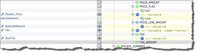
Using XSL-Variables to Pass on Value
The XML target file contains the elements <PRICE_LINE_AMOUNT>, <TAX>, and <TAX_AMOUNT> below the
<ARTICLE_PRICE> node.
There is no corresponding element in the XML source file for the <TAX_AMOUNT> element.
However, this value can be calculated by multiplying the <PRICE_LINE_AMOUNT> element and <TAX> element.
In principle, this does not require variables; however, this instance serves to demonstrate their use.
The values of the <Position_Price> and <Tax> elements from the input message are to be passed as variables.
Proceed as follows
-
Click the button in the center of the
<ARTICLE_PRICE>element line. -
The XSLT command wizard opens. The command wizard supports you when using all common XSLT commands. You can select the required command, configure it, and insert it into the XSLT script.
-
Click the
variablecommand. An explanation of the command is displayed with a list of the command’s attributes below it. -
Enter varLineAmount as the value of the
nameattribute and click OK. -
The command wizard closes and the variable appears beneath
<ARTICLE_PRICE>. -
Use Alt+
 to move the variable to the position above the
 <PRICE_LINE_AMOUNT>element. -
Since the variable value is to be assigned to the
<PRICE_LINE_AMOUNT>element, the variable declaration must be oved above this element. -
Assign the value of
<Position_Price>to the variable using thevalue-ofcommand. -
Assign the value of the
varLineAmountvariable to the<PRICE_LINE_AMOUNT>element using thevalue-ofcommand. When you call a variable, you have to prefix it with $:$varLineAmount. -
Proceed in the same way for the
<TAX>element.XML target should look like this:
Calculating the Value with XSLT-Operators
Because the <TAX_AMOUNT> element has no corresponding element in the input message, its value must be calculated.
To do so, you multiply the variables for the position price and tax rate.
Proceed as follows
-
Add the
value-ofcommand below<TAX_AMOUNT>. -
In the corresponding XML source line, enter the formula:
$varLineAmount * $varTax. -
Test the style sheet
Display the result of the calculation carried out. You will notice that the tax amount has only a single decimal place.
Using XSLT Functions
Formatting Numbers
-
XSLT provides the
format-number()function for formatting numbers. Use theformat-number($varLineAmount* $varTax,’0.00’)command to generate a result with two decimal places that uses a period as the decimal separator:
Counting Elements
-
The elements beneath
<INVOICE_SUMMARY>also have no corresponding elements in the input message and must therefore be calculated.The
<TOTAL_ITEM_NUM>element should specify the number of invoice items in the invoice. This value corresponds to the number of elements in the input message. You can use thecount()function to count the elements. Usecount(Invoice/Item)to count the number of invoice items.
Calculating the Sum
-
The
<TOTAL_AMOUNT>element specifies the total net amount for the invoice and is calculated from the sum of all position net amounts in the<Position_Price>elements. The sum of all values of a node set is calculated using thesum()function.
|
The sum is specified as a number ( |
The calculated sum must also be formatted as follows:
format-number(sum(Invoice/Item/Position_Price), '0.00')
Using Constants
-
To depict the
<TOTAL_TAX_AMOUNT>element, the values of<Position_Price>and<Tax>within each position must be multiplied. The results must then be added together. However, thesum()argument may only contain a node set and not a mathematical expression.We therefore assume that the tax rates within an invoice are identical and use a constant:
format-number(sum(Invoice/Item/Position_Price) * Invoice/Item[1]/Tax, '0.00')TheInvoice/Item[1]XPath expression causes the<Tax>value to be read from the first<Item>. This value is multiplied with the sum of the values of the<Position_Price>element. The result is formatted using theformat-number()function. -
Click Finish.
→ The module wizard closes and on the workspace an XSLT Converter icon is displayed.
|
Test your style sheet and connect the XSLT converter module with the CSV-XML module. |
Excursus: XSLT
Important XSLT commands
-
xsl:value-of: A value assignment. The value of the element in the incoming message is mapped to the corresponding element in the outgoing message. -
xsl:for-each: For the selected element, the same number of elements is created in the target structure as can be found in the incoming message.Example: If the value of the Item element in the incoming message is mapped to the Article in the outgoing message, this transformation is performed as often as the Item element is found in the incoming message. The Item elements must be found under the exact XPath indicated in the mapping.
-
xsl:copy-of: Copies a node, including its subordinate nodes and attributes, from the source file to the result. -
xsl:if: Indicates a condition. If this condition has been met, the corresponding structure is created on the right side. The condition is an XPath expression.Example: If there is a
<Price_Currency>element in the source structure, then the value of this element can be analyzed:Price_Currency='EUR'. -
xsl:choose-when: This instruction allows multiple cases to be differentiated. Enter anxsl:choose `on the right side. Enter an `xsl:whenand anxsl:otherwiseelement below thexsl:choose. Thexsl:whenelement can then be inserted as often as needed. Thexsl:otherwiseelement is optional. For eachxsl:whenelement, enter a condition on the left, as described for thexsl:ifinstruction. The target node is still belowxsl:choose, and must now be moved belowxsl:whenorxsl:otherwise. -
`xsl:result-document href=’myVar’ `(XSLT 2.0)
This instruction writes the result of the XSLT transformation to the
myVarworkflow variable. To make the variable available to following modules, themyVarworkflow variable must be defined at the workflow. -
{$variableName}
Within an attribute value, XPath expressions in curly brackets are evaluated and replaced by the returned value.
Optimizing XSLT style sheets:
Two aspects are key to improving performance:
-
efficient code
-
efficient use of the code
The following rules of thumb were created by Dr. Michael Kay. This recognized XSLT expert and developer of the Saxon XSLT processor is a member of the XSLT workgroup of the World Wide Web Consortium (W3C).
Writing efficient XSLT:
-
To output the text value of a simple
#PCDATAelement, it is better to use<xsl:value-of>instead of<xsl:apply-templates>. -
Do not sort the same node-set more than once. If necessary, save it as a result tree fragment and access it using the `node-set() `extension function.
-
Do not evaluate the same node-set more than once. Save it in a variable.
-
Avoid complex patterns in template rules. Instead, use
<xsl:choose>within the rule. -
Avoid the use of
//item. -
Avoid using
--or-→within comments as this will result in a syntactic error. -
If possible, avoid
<xsl:number>by usingposition(). -
Use
<xsl:key>for groupings. -
Be careful when using the preceding or following axes of coordinative nodes. This often indicates an algorithm with n-squared performance.
Using XSLT efficiently:
-
If you use the same source document repeatedly, keep it in memory.
-
If you have to perform the same transformation repeatedly, don’t. Use the result immediately instead.
-
Keep the source documents small. If necessary, split the documents.
-
Do not validate the same source more than once.
-
Keep the result file small.
-
Split complex transformations into several steps.
Creating a Technical Workflow 4: Storing the File in the File System
The invoices now exist in the correct format and need to be written to the Assembler AG file system using another File Connector.
Creating a File Connector
Proceed as follows
-
In the sidebar click Tools, open the System Connectors folder and drag a File Connector onto the diagram. The module wizard opens.
-
Enter the following:
-
Name: 1_Invoice openTRANS output
-
Input/output: xml
-
-
Click Next and select Output connector as the type in the next dialog, since the connector is to output the invoices. The connector status can remain as inactive as long as the workflow is not scheduled.
Ignore all further options and click Next to move to the next but one dialog. You can skip the Scheduler dialog.
-
Please make the following settings in the dialog File to Write:
-
In the Name field (in File Section), enter the value Invoice*.xml.
-
In the Name field (in Directory Section), enter a complete path.
This path must exist on the Process Engine system, and the user under whom the Process Engine is running requires write permissions for this directory.
-
-
Close the dialog by clicking Finish.
-
Connect the File Connector with the previous module.
Publish your modules after important configuration steps to save different work states. Testing of the complete Technical Workflow can only be successful if all elements and the workflow itself have been published.
Test the Technical Workflow again. If the test is successful, you have now created your first complete workflow.
End-to-End Navigation: Connecting Technical Level with Business Level
This section describes how you link your Technical Workflow with its business-related description in the business process diagram.
This linking allows you to give a professional opinion on errors that occur during the workflow’s execution by navigating top-down from the business process to its technical implementation.
Proceed as follows
-
Display the Main Order Transaction business process diagram on the Local tab for editing.
-
To the right of the workspace in the sidebar, open the docking window Links.
-
In the link directory, select the 1_Invoice Supplier A Technical Workflow.
-
Drag it onto the Receive invoice message event. A dialog appears and displays the Technical Workflow.
-
Select the connection line between the first and the second module to monitor the Invoice CSV-XML module.
-
Open the context menu and select Set link point.
-
Click OK to close the dialog.
-
Publish the BPD.
→ A colored link point is displayed in the Receive invoice activity, indicating a connection to a Technical Workflow:
|
Click the link point to display the linked Technical Workflow. In the Technical Workflow a link for jumping back to the BPD was added. |