Technical Workflow Diagrams
Usage
You use Technical Workflows to implement your business models, which are available e.g. as a Business Process Diagram.
You can link a Technical Workflow to the corresponding business model to categorize any errors that might occur during operation.
|
For an introduction into the Technical Workflows topic, refer to Integrating Systems and Automating Processes. |
Signaling changes in linked diagrams
If your business model is linked to a Technical Workflow, changes to the business model are indicated in the Technical Workflow.
Modularizing Technical Workflows
You can modularize Technical Workflows and reuse the modules in different Technical Workflows.
Configuring the execution
From each Technical Workflow, several instances can be executed in parallel. You specify the execution properties in the workflow diagram.
Refer to Execution Tab - TWF Only
Human workflows
You use task generators to integrate employees or business partners into your Technical Workflows.
Refer to Task Generator
Ad-hoc processes
You can start processes spontaneously using the Task List of the portal, if you have configured modules contained in these Technical Workflows accordingly. By doing so, you can, for example, create new tasks anytime.
Refer to Creating Ad Hoc Processes.
Validating Technical Workflows
You can let Technical Workflows validate. In doing so, the following aspects are checked:
-
Are there Demultiplexers without otherwise branches?
-
Are there If elements without else branches?
-
Are there deadlocks?
-
Do the links work?
Refer to Validating Diagrams - Syntax Check
Tools in Technical Workflow Diagrams
| Name | Description | Refer to |
|---|---|---|
Switch |
By using a Switch, you can control the message flow depending on one or more conditions. For this purpose, you create several sub-processes in the Switch element and define for each sub-process on which conditions the sub-process is to be executed. When configuring the conditions, you can define in which order the sub-processes are to be checked. As a rule, the first sub-process whose conditions are met is always executed. |
|
If |
Use the If tool to make further process execution depending on conditions. In the If tool, you can create several sub-processes. For each sub-process, you define one or more conditions. When configuring the conditions, you can define in which order the sub-processes are to be checked. As a rule, the first sub-process whose conditions are met is always executed. |
|
While |
The While tool contains a sub-process, checks the given break condition before it executes the sub- process and repeats the sub-process as long as the break condition is not fulfilled. |
|
Repeat Until |
The Repeat-Until tool contains a sub-process, executes it once, then checks the given break condition and repeats the sub-process until the break condition is fulfilled. |
|
For Each |
The For-Each tool contains a sub-process and executes it until a given final value is reached. Incrementing starts at a given start value. If the start value is greater than the final value, the loop is not executed at all. Start or final values must be positive, otherwise an error is thrown. All For-Each tools implicitly contain a scope, thus, you can define an error and compensation exit. |
|
Flow |
By using the Flow tool, you can execute two (or more) sub-processes in parallel. |
|
Pick |
By using the Pick tool, you define that the workflow has to wait for a message. The Pick tool can make a difference between message types, since it includes one or more OnMessage modules, each with a corresponding message type assigned to it, which is to be waited for by the Pick tool. |
|
Scope |
A scope combines several activities to one unit to which you can assign common error handling and compensation. |
|
Transaction Scope |
You can use a Transaction Scope to summarize to one transaction the actions of several database-based system connectors that access the same database.
|
|
Partner Management |
Using partner management you can integrate large numbers of external business partners into the supply chain and thus into your company’s business processes. The partner management helps you performing the following tasks:
|
|
Frame |
For visually grouping elements that belong together content-wise. |
|
Comment |
For adding a note anywhere on the workspace. |
|
Text |
For inserting user-specific texts that can be placed anywhere on the workspace. |
Using Switch Elements
By using a Switch you can control the message flow depending on one or more conditions. For this purpose, you create several sub-processes in the Switch element and define for each sub-process on which conditions the sub-process is to be executed.
When configuring the conditions you can define in which order the sub-processes are to be checked. As a rule, always the first sub-process whose conditions are met is executed.
To catch errors you can define a sub-process, which is always to be executed if none of all conditions at the other sub- process is met. This sub-process is called otherwise branch:
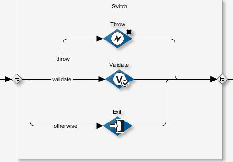
If no condition defined in the Switch applies and if there is also no otherwise branch the execution is continued at the end of the switch.
|
You can change the background color, line color and line type of switch. |
Proceed as follows
-
From the sidebar open the Tools docking window, click Tools and drag the Switch element into the working space.
-
Create the sub-processes in the Switch.
-
Connect the first modules of the sub-processes with the Switch entry.
-
Connect the modules at the end of the sub-processes with the Switch exit.
-
To define the conditions, proceed as follows:
-
Select a connection between the Switch entry and a sub-process.
-
Open the context menu and select Edit switch configuration. Alternatively, double-click the connection. The following dialog is displayed:
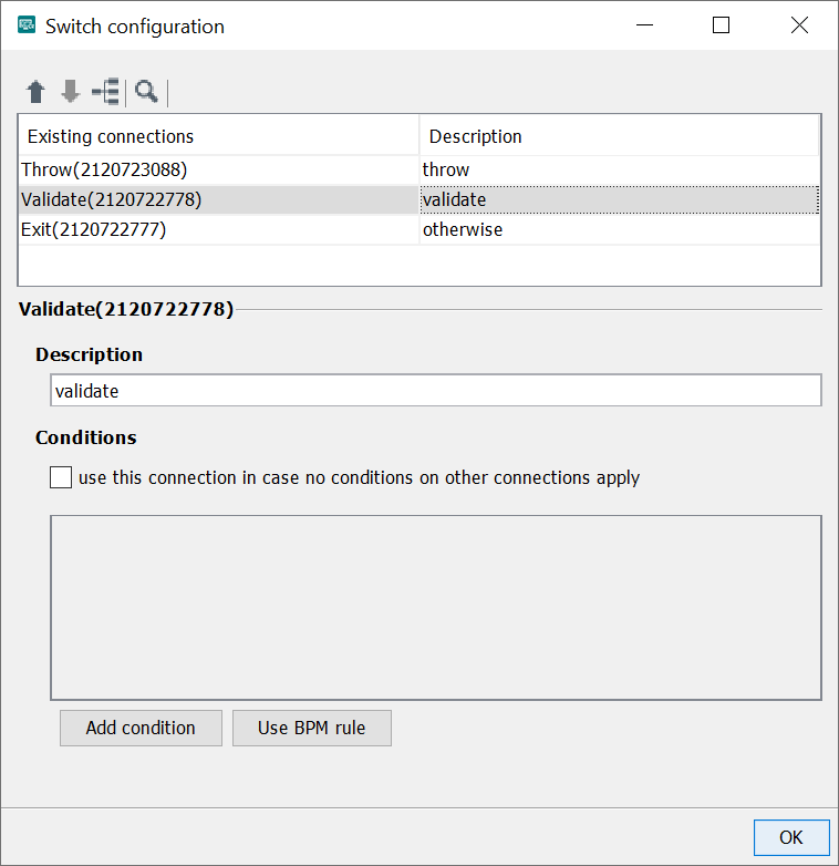
For explanations on the controls refer to Dialog Demultiplexer Configuration.
-
-
Click OK to close the dialog.
Using While Loops
Using a While loop you can let workflows or parts of them execute repeatedly. The workflow is repeated until a cancel condition is reached.
The cancel condition is checked before the workflow is executed. Thus, a workflow may not be executed at all because the cancel condition is already met.
|
If the cancel condition is never attained or has not been defined, the workflow will be repeated infinitely! |
In order the make the number of executions dependent from a counter variable, use an XSLT Converter or the variables mapping for incrementing or decrementing the variable value.
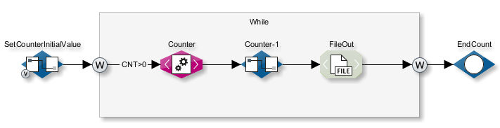
Example
In the example shown, the loop is executed until the value of the Counter variable (of the String type) is greater than the string 0 (Null).
After every pass the XSLT Converter reduces the value of counter by 1 and inserts it in a text node.
The value of the text node is reassigned to the counter variable in the following assign module.
The current value of counter
is then compared with the condition counter greater than string 0 before every pass.
Proceed as follows
-
From the sidebar open the Tools docking window, click Tools and drag the While element into the working space.
-
Drag the modules whose actions are to be repeated onto the While element.
-
Connect the first module to the While loop entry (on the left) and the last module to the exit (on the right).
-
To define the cancel condition, double-click the connection between the entry and the first module. The following dialog opens:
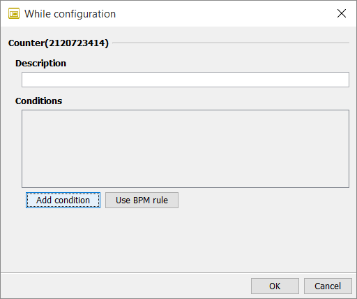
-
Enter a description for the condition. The description is shown on the connection line. If no description is given, the condition itself is displayed.
-
Add condition (button)
Shows the following control fields for defining conditions:
Operator: For connecting two or more conditions.
-
AND: All conditions must apply.
-
OR: One of the conditions must apply.
-
-
Button D: The condition applies to an element in the XML based data stream. In the input field, an XPath expression to must be entered.
If there is a sample XML file, click on the button and select the element interactively.
-
Button V: The condition applies to a system variable. The list offers all system variables.
-
Button X: The condition applies to an XPath expression The XPath is processed on an empty document, not on the data stream. The
 button opens a wizard for creating the XPath expression.
 -
Operator selection box
Selects an operator for a value comparison. The following operators can be selected:
Operator Meaning =
equal to
<
less than
>
greater than
>=
greater than or equal to
⇐
less than or equal to
!=
not equal to
Exists
exists
NotExists
does not exist
XPath
XPath expression
-
Buttons D and V: See above.
-
Button S: The condition applies to a string.
Example:
-
/ORDER/ORDERTOTAL > 1000 -
/ORDER/DELIVERY/ = Express -
/IBISProfile/Profile/Name ExistsIf the Name node exists in the incoming message, then the loop is carried out again.
-
count(/Order/test1) > 1If the XPath function’s count analysis shows that the` /Order/test1` node exists more than once, then the while loop is carried out again.
-
-
Close the dialog. The condition is shown on the connection line.
-
Insert an XSLT converter module in which the value of the counter is increased or reduced.
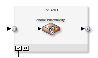
Using For Each Loops
Usage
To execute a sub-process until a given final value is reached, add a For Each loop from the Tools sidebar.
All For Each tools implicitly contain a scope, thus, you can define an error and compensation exit as well as variables with a life span limited to this tool, refer to Workflow Variables and Mappings.
Call up
To configure the For Each module properties, double-click the connection between the left F sign and the first module within the For Each frame.
Example
Dialog description
-
Counter name
Enter a unique name for the counter.
-
Start value of counter
-
Button D: The value applies to an element in the XML based data stream. In the input field, an XPath expression must be entered.
If there is a sample XML file, click on the
button and select the element interactively. -
Button V: The value applies to a variable. The list offers all variables.
-
Button X: The value applies to an XPath expression. The XPath is processed on an empty document, not on the data stream. The
button opens a wizard for creating the XPath expression. -
Button S: The value applies to a static value.
-
Final value of counter
Refer to Start value of counter above.
-
Use completion condition
To define a value that stops the execution of the For Each loop. If checked, the execution stops if the number of executions has reached the given value.
The value is ascertained only once when executing the loop for the first time, e.g. from an XPath. In the following executions the ascertained value is compared with the current number of executions.
Refer to Start value of counter above.
Handling and Suppressing Errors
In each workflow, there can be exceptions to the expected execution time. To handle these exceptions, the INUBIT software offers various powerful mechanisms for error handling and restoring.
Error analysis
By default, all workflows where an error that is not handled occurs in a module during execution are displayed with the Error status in the Queue Manager. The execution of the workflow is terminated.
To analyze the error, the Queue Manager displays all process steps to the error, the current message including the workflow variables in the module with the error and the error message.
You can restart the unsuccessful workflow with a new or changed file in the Queue Manager.
Notifications in case of an error
In case of errors in workflow executions, the INUBIT software can automatically send notifications to the owner of the workflow and the system administrator (root).
Refer to Alerting
Error variables
In case of errors, error variables are generated, which you can evaluate using Variables Mapping.
Refer to System Variable Overview
Avoiding connection errors
If the connection to an external system cannot be established you can configure the system connectors to retry to connect automatically. During the retry, the process has the status Retry in the Queue Manager. For each attempt to connect the entry in the Queue Manager is updated. For each unsuccessful attempt the counter is incremented.
Refer to Dialog System Connector Properties
Error handling
For system connectors and modules you have the following options for handling errors so that the workflow is stable and continued after an error occurs:
-
Substitute connector for system connectors
You can assign another system connector to a system connector as a substitute connector. If an error occurs, the substitute connector is executed after the last failed retry attempt. That way, the workflow can be completed successfully despite the error.
Refer to Using Modules as Error Branches.
-
Error branch on modules
You can define an error branch for each module. When an error occurs, the execution of the workflow is continued at the error branch with the inbound message of the module. You can query the error status via workflow variables.
Refer to Using Modules as Error Branches.
-
Throw modules for defined errors
A throw module generates an error that can be caught by the error branch of a scope or module or by a workflow connector.
Refer to Throw
Cross-module error handling and compensation
You can define a joint validity area, called scope, for several connected modules and thus control error handling and compensation across modules.
Suppressing errors
If an error in a module or scope is already caught and handled by one of the described mechanisms, you can specify that the error is to be suppressed in the module or scope. With this configuration, the workflow is continued at the error branch and the workflow execution is rated as successful. The incorrect workflow execution is shown in the system log but it generates no entry in the Queue Manager.
-
Suppressing Errors in Modules: Refer to Dialog General Module Properties
-
Suppressing Errors in Scopes: Refer to Configuring Error Handling in a Scope.
Handling errors in linked workflows
If the execution of a workflow that is linked to another workflow through a workflow connector is terminated with an error, the configuration of error processing and the workflow call stack on the workflow connector decide how the process continues.
Using Modules as Error Branches
You can define a second error branch for each module. In case of an error, the error branch receives the input message and the error message of the module with the error and can process these.
Alternatively, you can use a Scope to handle errors, refer to Configuring Error Handling in a Scope.
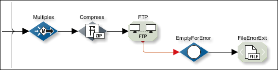
Example
In the example below: compressed messages are sent to an FTP Connector. If the FTP Connector throws an error, the compressed messages are forwarded to the error branch and saved in the file system by the File Connector. The error message is stored in a system variable.
Refer to Workflow Variables and Mappings
Proceed as follows
-
Add the module whose errors you want to process and at least one module you want to use as the error branch to the workflow.
-
Press the Ctrl key while selecting first the module whose errors you want to process and then the first Module of the error branch.
-
Open the context menu of one of the marked modules and select Connect as error branch.
→ The two modules are connected as error branch.
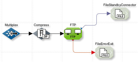
Using a System Connector as the Standby Connector
You can define standby connectors for all system connectors. A standby connector is another system connector that takes over the tasks of the primary system connector if they could not be executed successfully. There can also be a standby connector for every standby connector.
Example
In the example below, compressed messages are sent to an FTP Connector. If the FTP Connector is not available, the compressed messages are forwarded to the standby connector which saves them in the file system.
|
If both a standby connector and an error branch have been defined for a system connector, both are used: first the error branch and then the standby connector. |
Refer to Workflow Variables and Mappings
Proceed as follows
-
Insert the system connector and the standby connector into the workflow.
-
Hold down the Ctrl key and use the mouse to first select the system connector and then the standby connector.
-
Open the context menu and choose Connect as standby connector.
→ The connection to the standby connector is established.
Handling and Compensating Errors with Scopes
In Technical Workflows, you can define a common validity area (scope) for several connected modules and thus control the following aspects across modules:
-
Error handling
All modules in a scope can use the error branch of the scope. Each type of error can be handled individually at the error branch.
-
Compensation
You can use the Compensate Scope or Compensate module to define a rollback mechanism. When this happens, the scope is exited without generating an error.
-
Encapsulating workflow variables
For information about the handling of variables in scopes refer to Validity scope of workflow variables.
-
Suppressing Errors
You can centrally activate the suppression of errors for all modules of a scope.
Scopes can be nested and are then processed from the inside outwards.
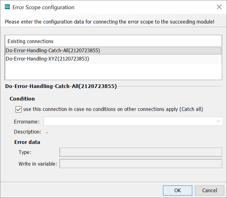
Configuring Error Handling in a Scope
The error branch of a scope captures errors thrown by modules in the scope that are not handled by error branches of the modules themselves. Errors that are captured by error branches are not passed on to the scope in which the modules are placed.
If an error occurs within a scope, it is checked if there is a matching workflow at the error branch of the scope. If this is not the case, the default exit is used (if there is one).
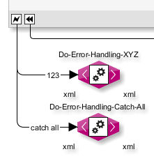
Example
Module A in the scope throws error 123. This is handled by the Do-Error-Handling-XYZ module in the error branch 123 of the scope. No corresponding error branch is available for errors other than 123, so for all other errors the catch-all branch is used.
Proceed as follows
-
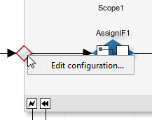
Drag the module with which an error is to be handled onto the Designer workspace.
-
Connect the module with the scope’s error symbol
 .
. -
Open the connection line’s context menu, then select Edit configuration. Alternatively, double-click the connection. The following dialog is displayed:
-
In the list, the module with which you have connected the error branch is displayed. The first module that you connect with the error exit is configured as catch all, by default. This exit makes sure that all errors are caught. With each additional module, you can handle one error more specifically.
You do not have to configure all errors individually and open the dialog multiple times. Instead, you can create all instances of error handling, connect them to the error branch, then configure them all in the same dialog by selecting all connected modules in the list, one by one, and assigning them each an error name.
-
In the Error name field, enter the name of the error or select one of the existing error names: In the list, error names from Throw modules, and Web Services Output Connectors are displayed. For other modules, you find the error name within the system variable `ISErrorString `after running a test. The fields in the Error data section only refer to errors thrown by a Throw module or a WebService Connector module.
These error data fields are used mainly to catch errors that are thrown by a Throw module or a Web Services Connector located in a Scope.
If a Web Services Connector is placed within a Scope and if one or several possible error returns are defined in its WSDL, these error names are displayed in the Error name combo box.
Each error has a defined error data type that is displayed in the Type field. You can define that the error data are saved to a variable of this type. In addition, the
ISErrorTextandISErrorStringvariables are written.For Throw modules located in the Scope, the error names configured therein are also displayed in the Error name combo box.
-
Default error exit: In order to capture errors for which no special error branch has been created, check the Use this connection if no conditions on other connections apply (Catch all) checkbox.
If you have two nested scopes and no default exit can be found for a scope within another scope, then the default error exit of the outer scope is used.
-
-
Click OK to close the dialog.
→ The error name is displayed on the connection line.
Configuring Compensation in Scopes
The compensate scope allows to undo changes made in the scope by one or more modules in case of an error. This is the equivalent of the rollback mechanism in transactions.
Functional principle
If there is a sequence of scopes containing individual actions and an error occurs within one action, then the actions are rolled back by a specific workflow. This workflow must be connected with the Compensate exit of the corresponding scope by a Workflow Connector. In the Workflow Connector the module must be configured which is suitable for the erroneous action. The scope containing the actions must be contained in another scope. For this scope an error exit with a Compensate module must be defined.
Example
After an erroneous action in the ScopeC the action in ScopeB is rolled back and then the action in ScopeA.
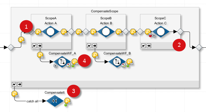
-
The actions in ScopeA, ScopeB and ScopeC are executed.
-
The action in ScopeC returns an error.
-
The error is handled by the error exit of the CompensateScope by the Compensate module CompensateIt.
-
The Compensate module takes care that for all scopes the Workflow Connectors are started which are connected with the corresponding Compensate exit and that the workflows contained in the scopes are executed.
The actions in the scopes are rolled back in reverse order compared to the workflow execution, that means first ScopeB and then ScopeA.
Proceed as follows
-
Drag all modules executing the actions that should be compensated into one or more scopes (in the example the scopes ScopeA, ScopeB and ScopeC).
-
Create another scope (in the example the scope CompensateScope).
-
Drag the scopes containing the actions into the scope created in step 2.
-
Connect the scopes.
-
Insert a Compensate module (in the example the module CompensateIt).
Refer to Compensate
-
Connect the Compensate module with the error exit of the scopes CompensateScope.
In order to roll back only a selected action when a specific error occurs, you can also use the Compensate Scope module.
-
Define the workflow which rolls back the changes, if required with a separate module for each scope.
-
Connect the workflow with a Workflow Connector (in the example the Workflow Connector CompensateWF) with the compensation symbol
 of the scopes, whose actions should be rolled back in case of an error.
This workflow is activated as soon as an error occurs in one of the contained scopes.
of the scopes, whose actions should be rolled back in case of an error.
This workflow is activated as soon as an error occurs in one of the contained scopes.
Configuring Error Suppression for All Modules in a Scope
For information about the effects of error suppression refer to Handling and Suppressing Errors.
Proceed as follows
-
Double-click the scope properties icon on the scope:
-
A dialog opens.
-
Select the option Consider workflow as successful despite processed Error Scope.
-
Click OK to close the dialog.
→ On all modules in the scope, a flash symbol indicates that error suppression is active.
Managing Transactions with the Transaction Scope
You can use a Transaction Scope to summarize the actions of several database-based system connectors that access the same database to one transaction:
-
If the actions of all connectors in the Transaction Scope are executed successfully, the transaction is confirmed.
-
Otherwise, the transaction is rolled back.
Supported system connectors
In each Transaction Scope, you can use the following system connector:
-
Database Connector with activated transaction mode
Error in the Transaction Scope
A Transaction Scope has a rollback exit that can be connected to a module. The execution of the module at the rollback exit is triggered by each rollback and by the following events:
-
Undefined error in the execution of modules in the Transaction Scope.
-
A throw module in the Transaction Scope is executed, handling a defined error.
Refer to Throw
-
The timeout of the Transaction Scope is exceeded.
The execution of the modules within the Transaction Scope took longer than permitted by the timeout of the Transaction Scope.
If no module is defined at the rollback exit, the execution of the workflow is interrupted and an error is generated in the Queue Manager.
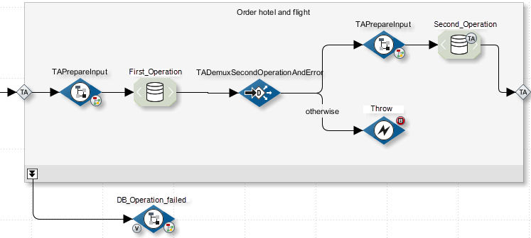
Example
This workflow is first used to book a hotel room (Database Connector First_Operation) and then a suitable flight (Database Connector Second_Operation). If no hotel room is available, a throw module is executed and thus triggers a rollback of the transaction. The Workflow Connector is then executed at the rollback exit and sends an info e-mail to the person responsible.
Prerequisites
You can only summarize transactions of Database Connectors in a Transaction Scope if the connectors access the same database!
Proceed as follows
-
Insert a Transaction Scope into your Technical Workflow.
-
Create and configure the modules in a transaction scope.
-
Connect the first module in the Transaction Scope with the entry of the Transaction Scope and the last module with the exit of Transaction Scopes.
Activate transaction mode
-
Open the context menu of a Database Connector and choose Set transaction mark.
|
Activate transaction mode for all Database Connectors within the Transaction Scope! If transaction mode is not active, the system connectors work as usual and the transactions are not summarized! |
Define a timeout
-
Double-click the TA symbol of the Transaction Scope entry. A dialog opens.
-
Enter the timeout.
-
Click OK to close the dialog.
-
Publish the workflow.
Refactoring: Connecting Technical Workflows to Workflow Connectors
Refactoring offers the possibility to improve the structure of existing Technical Workflows subsequently without modifying their behavior. By doing so, you can optimize readability and maintainability of Technical Workflows and thus significantly reduce the expense for error analysis and functional extensions.
Refactoring means to transfer selected modules into a newly created Workflow. Both Workflows are connected with each other by a Workflow Connector.
If you transfer system connectors, their names may get postfixes in order to keep them unique.
|
One system connector is available in only one Technical Workflow, because the INUBIT licensing mechanism allows a system connector to be used in just one workflow. If you copy system connectors you need additional licenses. Thus, outsource system connectors in separate workflows. You can access the system connector workflow by using a Workflow Connector from any other module in a Technical Workflow. |
Proceed as follows
-
Display the Technical Workflow in a local directory.
-
In the source workflow select all modules, which are to be transferred into the new Technical Workflow.
-
Open the context menu and select Replace by Workflow Connector. The wizard for creating a new Workflow Connector opens.
Refer to Workflow Connector
-
Name the Workflow Connector and let you guide by the wizard through the creation of the new workflow and the workflow connector.
→ After finishing the wizard the source workflow is displayed. The new Technical Workflow containing the transferred modules was added to the same directory.
Configuring the Variable Transfer for Linked Technical Workflows
Usage
In each Technical Workflow, you can define whether all variables or only selected variables are to be transferred to the workflow when a workflow is called. You also specify whether the workflow variables are to be returned to the calling workflow.
You can use this function to encapsulate workflow-related variables and avoid errors that can be caused by uncontrolled forwarding of variables.
Procedure
-
Encapsulate workflow
You configure the variable transfer in the workflow in the Variables docking window.
Refer to For jump into this workflow
|
The following applies to workflows that were created in the INUBIT software: The variable transfer for linked workflows is restricted by default, that is to say, only variables that are explicitly defined as input/output variables are transferred or accepted. The following applies to workflows that were created in INUBIT versions < 5.3: The variable transfer is not restricted, that is, all variables are transferred and accepted. |
-
Define input and output variables
If you have encapsulated the workflow, you must also specify for all module variables and self-defining variables whether these are workflow input or output variables or both:
-
Workflow input variables are variables that the sub-workflow needs for execution. These variables must be provided and transferred by a calling workflow.
-
Workflow output variables are variables that the sub-workflow returns to the calling workflow. Output variables are only returned if the sub-workflow is called synchronously.
Refer to Dialog Descriptions Workflow Connector.
-
-
Configure the variable transfer
In the workflow connector of the calling workflow, you specify how the values for the workflow input variables are transferred to the sub-workflow and how the value of the output variable is copied to the calling workflow. When the sub-workflow is called it is checked whether all required input variables have been transferred. If this is not the case, a corresponding error message is output.
Prerequisites
At least two linked workflows already exist.
Proceed as follows
-
Open the sub-workflow for editing.
Always start with the bottom workflow to define the variable transfer. The bottom workflow is that which is called by one or more workflows but does not call any other workflows itself.
Encapsulate workflow
-
Open the Variables docking window and ensure that the Only use input/output variables option is selected in the For jump into this workflow area.
-
Define a variable or edit an existing one.
Refer to Defining Variables
Define the function of the variable
-
In the Variable definition dialog, display the Transfer upon workflow call tab.
-
Specify whether the variable is a workflow input variable or a workflow output variable or both.
Refer to Define input and output variables above.
-
Enter a standard value (data type string or XML) if the variable is a workflow input variable. The default value is used if the variable is transferred without a value:
-
Click OK to close the dialog.
In the Variables docking window, a symbol on the variable indicates its function.
-
Publish the workflow.
Configure the transfer on the Workflow Connector
-
Open the calling workflow for editing. The Variable mapping symbol V of the Workflow Connector is now highlighted in color.
-
Double-click the V symbol:
The dialog opens:
This dialog displays mapping rows for each of the variables defined as input variables or output variables in the linked workflow. These rows have a different background color.
For the input variables, any kind of mapping source can be selected in the Source section. If the input variable has a default value, it is pre-selected by default. Otherwise, in the Source column, the entry is highlighted in red to show that the expected input variable has not yet been assigned to a workflow variable in the current workflow.
To assign a Source, click the row with the desired mapping rule.
For the output variables, only a variable can be selected as the target.
By default, the “–” entry is pre-selected in the drop-down menu to indicate that the value of this output variable is not needed in the calling workflow.
In the Handling of input/output variables section, you can click the Create 1:1 mappings button to create same-named source variables for the input/output variables of the linked workflow.
-
Click OK to close the dialog.
Using XML Schemas from the Repository as References in Workflows
You can use one or more XML Schemas stored in the Repository as references in Technical Workflows, for example to define the structure of variables. In principle and if it exists, the workflows always use the active schema tag corresponding to the workflow tag, otherwise they use the HEAD version of the XML Schemas.
When using tagging
If a tag is active at a workflow, the one schema is used that is marked with the corresponding tag.
If no active tag is available, the HEAD version of the XML Schema is used.
Checking schemas in and out
You can edit the XML Schemas directly at the workflow. For editing a copy of the XML Schema is created.
After editing you can choose whether your changes are to be stored in the Repository and thus be available globally or whether the modified XML Schema should be used only locally by the current workflow:
-
Making changes in the XML Schema available globally
After editing, check in the XML Schema into the Repository.
-
Using the changed XML Schema locally
Do not check in the XML Schema. The workflow uses the local copy until you remove the copy and replace it by a reference to the XML Schema stored in the Repository.
Proceed as follows
-
Open the workflow for editing.
-
From the sidebar open the docking window Schemas.
-
Loading the XML Schema from the Repository:
-
Click the
 button.
A menu opens up.
button.
A menu opens up. -
Select Open from > Repository. The Repository Explorer opens.
-
Navigate to the XML Schema and load it. The XML Schema is displayed.
-
-
Click Edit.
The HEAD version of the XML Schema and buttons for checking in and discarding changes are displayed:
Edit the XML Schema.
-
To store the XML Schema back into the Repository click Check-In.
-
To reject the changes and to load the original XML Schema from the Repository, click Discard. After a confirmation prompt the currently displayed file is overwritten by the head version stored in the Repository.
-
Web Services
Call up
INUBIT Workbench > Designer > Sidebar > Web Services
| Option | Description |
|---|---|
PartnerLinks |
PartnerLinks contain the web services involved in a business process. A PartnerLink always consists of a local endpoint and a partner endpoint: Local endpoints are represented by Receive modules or Input Web Services Connectors. Partner endpoints are the Web Services that are invoked by Invoke modules or Output Web Services Connectors. |
WSDLs |
The WSDL file describes the operations, data and exchange protocols the Web Service offers. This information is machine readable. Based on this WSDL file service consumers create a SOAP request in order to access one of the Web Service’s operations. The Web Service processes the SOAP request and returns the result as SOAP response to the service consumer. |
CorrelationSets |
The Correlation mechanism is used with asynchronous Web Services to associate response messages to the workflow instance that has sent the asynchronous request. \nA CorrelationSet defines a business value (e.g. order number) that is determined from a soap message and that identifies a running workflow instance. \nThe value is made up of one or more Property values. Thus CorrelationSets define constants that are set during workflow execution. They are used to identify a running workflow instance. CorrelationSets are needed for asynchronous Web Service-Listener or Receive modules. A CorrelationSet is defined at the process (workflow) or within a Scope and named. Properties are assigned to a CorrelationSet. A CorrelationSet must be initiated explicitly at a Web Services Connector. The properties specified in the CorrelationSet are determined from the input message or the output message. Within a running workflow, all of the following Web Services Connectors that uses this CorrelationSet must use the same property values regarding it’s input message or output message. |
Properties |
Properties are parts of a CorrelationSet and contain unique values in a running workflow instance. The values can be order or customer numbers for example. The properties specified must be stored in a WSDL file. |
PropertyAliases |
A propertyAlias defines how a Property is filled with a value. To fill this value, you can use a WSDL message and an XPath which is applied on the message, for example. |
Symbols in Technical Workflows and in the Directory Tree
Symbols at Modules in Technical Workflows
| Symbol | Explanation | Refer to |
|---|---|---|
|
Output System Connector |
|
|
Input System Connector |
|
|
Medium System Connector |
|
|
Commented System Connector |
|
|
The construction site symbol indicates modifications at linked BPDs and TWFs. |
|
|
The module is an ad hoc process starter. |
|
|
A transaction marker at a system connector indicates that the system connector is executed in the transaction mode. |
|
|
Missing configuration at Workflow Connector. The linked workflow expects an input variable. This input variable must yet be assigned to a variable of the displayed workflow. |
|
|
If the symbol is displayed permanently: Variables have been created on the module. |
|
|
Workflow Connector is in asynchronous processing mode. |
|
|
Error supprsion is active |
|
|
The module is locked. You can neither edit it nor display its properties. A module is labeled as Locked if it is owned by a user group which is not visible for the currently logged-in user. For users only modules are visible which are owned by their own group or the group which is directly superordinated. This situation can come up this way, for example:
|
|
|
The scheduler icon is visible if the system connector
|
|
|
A metadata value of the type External document is displayed as an icon in the* lower left corner of the element. |