Business Object Diagrams
Usage
You use Business Object Diagrams (BO diagrams) to model business objects and their relationships as UML class diagrams.
You can link the BO Diagram to an XML Schema: Changes to the BO Diagram affect the XML Schema immediately, just like changes to the XML Schema are immediately displayed in the BO Diagram. The BO Diagram is therefore also a graphical XML Schema editor. The graphical display as a UML class diagram makes it easier to grasp the scope and complexity of your XML schema.
You can use your BO Diagrams in business and technical processes, for example, by linking the modeled business objects to data objects of a Business Process Diagram or using the XML Schema to check the syntax of the inbound and outbound messages in Technical Workflows.
Refer to
With the BO Diagram, you also create the basis for storing the business objects and generating suitable web-based interfaces:
-
Web-based interface
You can use the Task Generator to quickly and easily generate parts of forms from an XML Schema.
Refer to Generating Form Parts from XML Schemas or WSDL Files with the Client Generator.
General diagram functions
You can also use the general diagram functions in BO Diagrams, refer to:
Creating BO Diagrams with a Linked XML Schema
When you create a Business Object Diagram, you can link it directly to a blank XML Schema.
Proceed as follows
-
Create a Business Object Diagram. The diagram wizard opens.
Refer to Creating a Diagram. -
In the Business Object Diagram dialog select the XML Schema option.
In the Linked Schema field, the system automatically suggests a name and storage location for the XML Schema to be generated in the Repository. You can change both the name and the storage location.
-
If you wish, you can enter the target namespace of the schema in the Schema namespace field.
-
Close the dialog by choosing Ok.
→ An empty BO diagram and XML Schema are generated.
|
In addition to linear compositions, nested compositions can also be designed in a BOD. Each composition type will be highlighted in a different color. |
Importing an XML Schema and Displaying it as BO Diagram
Proceed as follows
-
Create a Business Object Diagram. The diagram wizard opens.
Refer to Creating a Diagram. -
In the Business Object Diagram dialog select the XML Schema option.
-
Next to the Apply schema data from field, click the button
 .
A file explorer opens.
.
A file explorer opens. -
Navigate to your XML Schema and load it.
-
Choose OK to close the dialog.
→ A BO Diagram is generated from your XML Schema and displayed. The XML Schema is stored in the specified path in the Repository.
Editing a Linked XML Schema
You can edit the XML Schema that is linked to your BO diagram directly from the BO diagram or from the Repository.
Editing a Linked XML Schema Directly from the BO Diagram
When you edit the XML Schema from the BO Diagram in the Schema Editor, you edit a local copy of the XML Schema.
When the BO Diagram is published, this copy is saved to the Repository as the most recent version of the XML Schema.
Proceed as follows
-
Select the BO Diagram in the local directory tree.
-
Open the context menu and choose Edit linked schema.
The XML Schema is displayed in the Schema Editor.
For information about the Schema Editor, refer to Schema Editor. -
Edit the XML Schema.
You can undo your changes at any time and return to the head version of the XML Schema, which is saved in the Repository. To do so, click Discard. -
After editing, choose OK to close the Schema Editor.
→ The BO Diagram is synchronized with the XML Schema.
Editing a Linked XML Schema in the Repository
You can open and edit an XML Schema that is linked to a BO Diagram from the Repository.
Refer to Editing content
When you save the changed XML Schema, a new version is generated.
These changes affect the XML Schema linked to the BO Diagram as follows:
-
BO Diagram is saved locally:
The XML Schema changes are not displayed because the BO Diagram is based on a local copy of the XML Schema not on the XML Schema saved in the Repository.To make the changes visible and to synchronize the BO Diagram with the latest version of the XML Schema in the Repository, open the linked XML Schema.
As long as the BO Diagram is not synchronized with the latest version of the XML Schema in the Repository, you will be informed accordingly when you publish the BO Diagram.
-
BO Diagram is published:
The XML Schema changes are not displayed. Instead, you will see a note stating the there is a later version of the XML Schema in the Repository.To make the changes visible and to synchronize the BO Diagram with the latest version of the XML Schema in the Repository, open the BO Diagram for editing and publish it again.
Importing Type Definitions from an External XML Schema
You can import type definitions from XML Schemas into your BO Diagram. The XML Schema must be accessible via a URL.
After the import, the types are available as follows:
-
For BO Diagrams without an XML Schema link:
You can use the imported types to type attributes, parameters and return values.Refer to
-
BO Diagrams with an XML Schema link:
You can use the imported types to type attributes, parameters and element definitions. The types are displayed, among other times, when you open the linked schema.
Refer to Editing a Linked XML Schema.
Proceed as follows
-
Select the Business Object Diagram in the local directory.
-
Open the context menu and select Import types from schema file.
-
Do one of the following, depending on whether you have a BO Diagram with or without an XML Schema link:
-
BO Diagram without an XML Schema link
A file explorer opens.
In the file explorer, navigate to your XML Schema and load it. -
BO Diagram with an XML Schema link
Another dialog opens:-
In the dialog, enter the URL of the XML Schema or click the button to reference an XML Schema from the Repository.
-
Choose OK to close the dialog.
-
→ The type definitions are imported.
-
UML Modeling Elements in BO Diagrams
Standards-compliant notation
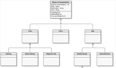
Business Object Diagrams are based on UML class diagrams as per UML 2.0.
For the UML class diagram specification refer to https://www.omg.org/spec/UML/2.2/Infrastructure/PDF.
For information about how the UML classes are mapped to XML Schema structures, refer to BOD-Mapping Tables: UML Element/XML Schema Element.
Tools in Business Object Diagrams
Business Object Diagrams have the following modeling elements:
| Symbol | Name | Usage |
|---|---|---|
|
Class |
A class describes a common structure and the common response of objects.
A class consists of a name, typed attributes and operations with parameters and return values. |
|
Generalization inherits from relationship. |
A subordinate class inherits from the higher-level class. The higher-level class is a generalization of the subordinate class. Subordinate classes can have additional properties as well as the inherited properties.
When you generalize, you make a connection from the subordinate class to the higher-level class. The arrow always points to the higher-level class. |
|
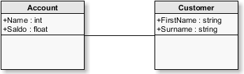
Association |
n-n relationship between objects of one or more classes. An object of a class can be linked to one or more objects of another class:
|
|
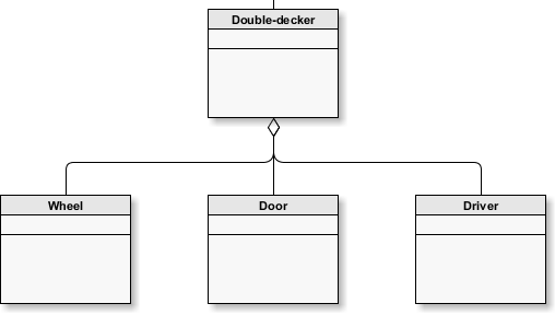
Aggregation |
consists of relationship. Special case of an association. To describe a class by means of its subordinate classes:
Draw a connection from the aggregate to the parts. The pound sign always points to the aggregate, hence, the higher-level class. |
|
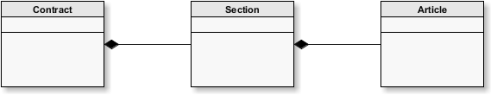
Composition |
is dependent on relationship. Special case of an association. Describes the relationship between a whole and its parts, whereby the higher-level object determines the conditions for the existence of the sub-object:
Draw a connection from the whole to its parts. The pound sign always points to the whole, that is, the higher-level class. |


Artifacts in Business Object Diagrams
You can use the following artifacts in Business Object Diagrams:
| Symbol | Name | Meaning |
|---|---|---|
|
Comment |
For adding a note anywhere on the workspace. |
|
Frame |
For visually grouping elements that belong together content-wise. |
|
Image |
For inserting a graphic of your choice. |
|
Text |
For inserting user-specific texts that can be placed anywhere on the workspace. |


BOD-Mapping Tables: UML Element/XML Schema Element
Element Declaration with Simple Content in Business Object Diagrams
| UML | XML Schema |
|---|---|
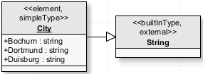
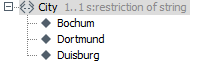
Class with stereotypes Element, Simple Type with generalization relationship with a class with stereotype External, BuiltInType:
|
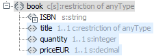
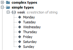
Element declaration with restriction to a simple type, e.g. value list:
|
Element Declaration with Reference in Business Object Diagrams
| UML | XML Schema |
|---|---|
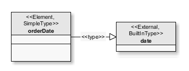
Class with stereotypes Element, SimpleType and named navigable association to a class with stereotypes External and BuiltInType:
|
Element Declaration with Reference to a Simple Type Definition:
|
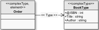
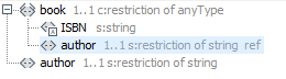
Class with stereotype Element and named navigable association to a class:
|
Element declaration with reference to a complex type definition:
|

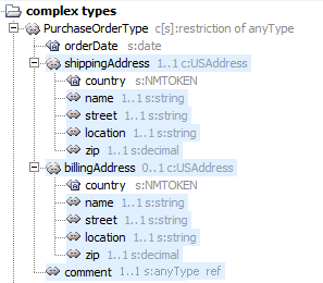
Element Declaration with Complex Content in Business Object Diagrams
Refer to Declaring an Element in Business Object Diagrams Object Diagrams.
| UML | XML Schema |
|---|---|
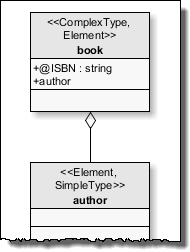
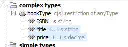
Class with stereotypes Element, Complex Type and composition relationship with a class with a complex element declaration:
|
Element declaration with inline defined complex content that consists of the inline defined sub-elements with simple or complex content.
|
Class with stereotypes Element, Complex Type
|
Element declaration with inline defined complex content that consists of sub-elements that reference a type
|
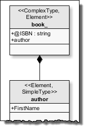
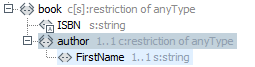
Class with stereotypes Element, Complex Type and aggregation relationship with a class with a simple element declaration:
|
Element declaration with inline defined complex content that consists of sub-elements with reference to a global element declaration
|
Definition of Simple Types in Business Object Diagrams
| UML | XML Schema |
|---|---|
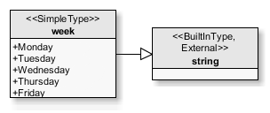
Class with stereotype SimpleType and generalization relationship with a class with stereotypes External, BuiltInType:
|
Simple type definition
|
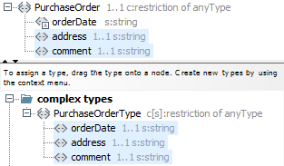
Definition of Complex Types with Attributes and Sub-Elements in Business Object Diagrams
| UML | XML Schema |
|---|---|
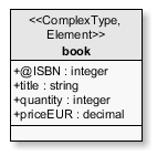
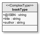
Class with stereotype Complex Type
|
Complex type with inline defined elements
|
Class with stereotype Complex Typ and aggregation relationship e.g. with classes with type definitions and element declarations
|
Complex type with element declarations in which a complex type and/or a global element declaration are referenced.
|
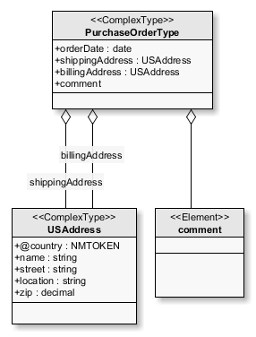
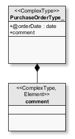
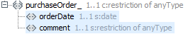
Class with stereotype Element, Complex Type and composition relationship e.g. with classes with element declarations
|
Complex type with inline declared sub-element.
|
Declaring an Element in Business Object Diagrams
By declaring an element, you specify the name and the content of the element in the instance document.
For an example refer to Element Declaration with Complex Content in Business Object Diagrams.
Prerequisites
The BO diagram is linked with an XML Schema.
Proceed as follows
-
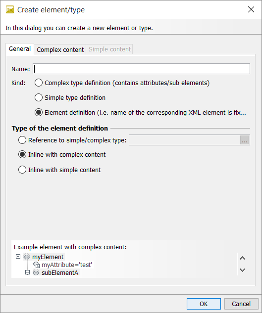
Insert a class. A dialog opens.
-
Enter the name of the element.
-
Make sure the Element definition option is selected. As a default this is the case.
-
Depending on the desired type of element declaration, choose one of the following options.
-
Reference to a simple/complex type
-
Click
.
A dialog with all available type definitions appears. -
Choose a type. Choose OK to close the dialog. The type is displayed.
-
Choose OK to close the dialog.
The element declaration with reference is displayed.For examples refer to Element Declaration with Reference in Business Object Diagrams.
-
-
Inline with complex content
-
Display the Complex content tab.
-
Declare the attributes and sub-elements.
For more information refer chapter to Declare attributes and Declare sub-elements.
-
-
Inline with simple content
-
Display the Simple content tab.
-
Specify the type of restriction, the basic type and the content.
For instructions, refer to Defining a Simple Type in Business Object Diagrams from the Display the Simple content tab step onwards.
-
-
-
Choose OK to close the dialog.
→ The element declaration is displayed.
Defining a Simple Type in Business Object Diagrams
You derive a new simply type definition from an existing simple type by restricting the existing type. The allowed value set of the new type is a subset of the value set of the existing type.
For an example refer to Definition of Simple Types in Business Object Diagrams
Prerequisites
The BO Diagram is linked to an XML Schema.
Proceed as follows
-
Insert a class. A dialog opens.
-
Enter the name of the type.
-
Select the Simple type definition option.
-
Display the Simple content tab:
-
Choose the basic type.
-
In the Content field, specify the type of content:
-
Enumeration
You see the options with which you can define the list of permissible values. -
Pattern
You see the input field for the pattern. Use regular expressions to define the pattern.
Refer to Regular Expressions. -
Other
If you choose Other you can define restrictions of your choice directly in the XML Schema.
-
-
Choose OK to close the dialog.
→ The simple type is displayed.
Defining a Complex Type with Attributes and Sub-Elements in Business Object Diagrams
You can define new complex types, which usually contain a set of element declarations, element references and attribute declarations.
For an example refer to Definition of Complex Types with Attributes and Sub-Elements in Business Object Diagrams
Prerequisites
The BO Diagram is linked to an XML Schema.
Proceed as follows
-
Insert a class. A dialog opens.
-
Enter the name of the type.
-
Select the Complex type definition option.
-
Display the Complex content tab:
Declare attributes
-
To create an attribute, in the Attributes area, click
 . Another dialog opens.
 -
Enter the name of the attribute.
-
To choose the type of attribute, click
. -
Choose OK to close the dialog.
Declare sub-elements
-
To select the type of composition, click on one of the options in Composition Type.
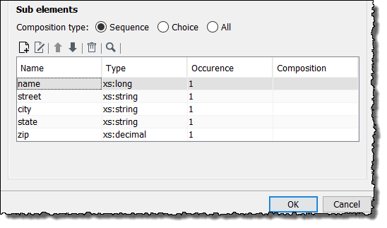
-
To specify the content of the type in the Sub-elements area, click
.
Another dialog opens.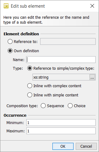
-
Specify how the sub-element is supposed to be defined:
-
The sub-element references an already existing element declaration: Select the Reference to option and choose an element declaration.
-
The sub-element is new; the content is specified through the reference to an existing type:
-
Select the Own definition option.
-
Enter a name.
-
Select the Reference to a simple/complex type option and choose the type.
-
-
The sub-element is new and complex because it has additional sub-elements and/or attributes:
-
Select the Own definition option.
-
Enter a name.
-
Select the Inline with complex content option.
A complex element declaration is generated from this information. You specify the content in a second step, after you have completed the current complex type definition.
-
-
The sub-element is new and simple because it contains data with a simple type:
-
Select the Own definition option.
-
Enter a name.
-
Select the Inline with simple content option.
A simple element declaration is generated from this information. You specify the restrictions of the element declaration once you have completed the current complex type definition.
-
-
-
In the Occurrence area, specify how often the sub-element may occur in the instances of the XML Schema. If the number can be indefinite, enter a * (asterisk) in the Maximum field.
-
Choose OK to close the dialog.
The new sub-element is displayed. -
To create additional attributes and sub-elements, repeat these steps.
-
Choose OK to close the dialog.
The complex type definition is displayed. -
If you have created sub-elements with a simple or complex type, you can now define these sub-elements more specifically: To do so, click the sub-elements. Refer to Declaring an Element in Business Object Diagrams.
Creating Connections in BO Diagrams with XML Schema
Creating Associations in Business Object Diagrams
To specify the type of an element declaration by means of a reference to a simple or complex type definition, you connect the corresponding classes as an association.
Proceed as follows
-
Hold down the Ctrl key while you first select the class whose type is to be defined, and then the class in which the type is defined.
-
Open the context menu and choose Connect as > association.
→ Both classes are connected by an association.
Creating Compositions in Business Object Diagrams
To add an element declaration as a sub-element to a complex element declaration or to a complex type definition, connect the corresponding classes as a composition.
Proceed as follows
-
Hold down the Ctrl key whilst you first select the class that is to be added as a sub-element, and then the class to which the sub-element is to be added.
-
Open the context menu and choose Connect as > composition.
→ Both classes are connected by a composition.
Refer to
Creating Aggregations in Business Object Diagrams
To add an element declaration as a referenced sub-element to a complex element or type declaration, connect the corresponding classes as an aggregation.
Proceed as follows
-
Hold down the Ctrl key whilst you first select the class to which the sub-element is to be added, and then the class that is to be referenced as the sub-element.
-
Open the context menu and select Connect as > aggregation.
→ Both classes are connected by an aggregation.
Refer to
Creating Connections in BO Diagrams without XML Schema
Connecting Classes in Business Object Diagrams
You can connect classes to each other as generalization, association, aggregation or composition.
Refer to UML Modeling Elements in BO Diagrams.
Proceed as follows
-
Select the two classes that are to be connected.
-
Open the context menu and choose Connect as > [generalization|association|aggregation|composition].
Creating a Self-Referencing Connection in Business Object Diagrams
You can connect classes to themselves as association, aggregation or composition.
Proceed as follows
Open the context menu of the class and choose Add > [association|aggregation|composition].
Editing Connections in Business Object Diagrams
Depending on the type of connection between two classes, you have the following options for editing the connection:
-
For all connection types:
Name the connection to improve the readability of the diagram. -
For associations, aggregations and compositions:
-
Name the start and end of the connection e.g. with role names
-
Enter multiplicity and thus specify how many objects of the class are connected to how many sub-objects
-
Proceed as follows
Double-click the connection.
→ A dialog for editing the connection appears.
BO Diagram without Schema: Reusing Type Definitions
You can import data types from other BO diagrams and use them to type attributes as well as parameters and return values of operations.
Proceed as follows
-
Enter a name for the Business Object Diagram. The name must start with the prefix
_Base, e.g._BaseArticleOrder. -
Publish the diagram.
The classes from the _BaseArticleOrder diagram are now available as data types in the same diagram and in all others.
If e.g. in the _BaseGeometricShape Business Object Diagram, the classes triangle, square, circle and oval are defined, then these classes are now available as attribute types.
Dialog Descriptions in Business Object Diagrams
Dialog Association in Business Object Diagrams
In this dialog, you can edit the connection between two classes. Among other things, you can change the type of the connection, name of the connection, its start and end or specify multiplicity for start and end.
Tabs
The dialog consists of the following tabs:
-
Association
-
Type: Association, aggregation and composition are available.
Refer to Tools in Business Object Diagrams. -
Name: Name of the connection, is initially displayed in the middle of the connection and can be moved.
-
Description: Is displayed as a tooltip above the line in the diagram and in the comment area of the designer.
-
-
Association start
-
Name: Name of starting point.
-
Description: Explanation for the association start.
-
Visibility:
Refer Class Tab in Business Object Diagrams. -
Multiplicity:
Refer Class Tab in Business Object Diagrams. -
Modifier:
-
static: When checked, the association remains even if the source instance was deleted.
-
navigability: When checked, an arrow indicates that the connection is navigable in the direction of the association start. If the connection is navigable both-way, no arrow is displayed. Each connection must be navigable at least in one direction.
-
Specifies whether an arrow shape according to the connection type is displayed at the start of the association.
-
-
Initial value: Initial value of the multiplicity.
-
-
Association end
As association start but for the other end of the association.
Class Element - without Linked XML Schema
Class Tab in Business Object Diagrams
-
Name
Name of the class. -
Description
Descriptive comment for the class. The comment is displayed as a tooltip above the element in the diagram and in the comment area of the designer. -
Visibility: Defines the access type to the class:
-
public: Visible to all objects.
-
private: Visible only to objects of the class.
-
protected: Visible only to objects of the inheriting class.
-
package: Visible within the package.
-
-
Modifier
-
abstract: The class cannot be instantiated directly.
-
static: Only one object can be created from the class.
-
final: The class cannot be inherited directly.
-
Stereotypes Tab in Business Object Diagrams
This tab shows all available stereotypes. You can add as many stereotypes as you wish. Only selected stereotypes refer to the current class.
You can use a stereotype e.g. to define the usage connection of the class. By using a stereotype, you extend a class to a new element of the UML model.
Stereotypes are displayed above the class name in double, pointy brackets (<< >>) e.g.:
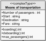
The displayed stereotypes can be seen and used in all classes in all Business Object Diagrams of your user area, group or higher-level group.
Attributes Tab in Business Object Diagrams
This tab shows all the attributes of the class. You can add attributes, edit existing attributes and change the order of the attributes.
Toolbar
-
Adds a new attribute.
-
 : Opens a dialog for editing the selected attribute:
-
Name: Name of the attribute.
-
Description: Descriptive comment.
-
Visibility (for unrestricted BODs only): public, private, protected and package
Refer to Class Tab in Business Object Diagrams. -
Type: Any data type.
-
Multiplicity:
Specifies whether there can be one or several objects of an attribute:
-
1: The attribute has exactly one object.
-
1…*: The attribute has at least one object but can have an unlimited number.
-
0…1: The attribute has no objects or exactly one object.
-
*: The attribute has no objects or any number of objects.
-
-
Default value: Default value of the multiplicity.
-
-
 /
/ : Moves the selected attribute up or down one position in the list.
 -
 : For deleting the selected attribute.
Operations Tab in Business Object Diagrams
This tab displays all operations available to the class. You can edit operations or add new operations.
Toolbar
-
: Adds a new operation.
-
: Opens a dialog for editing the selected operation.
Refer to Operation in Business Object Diagrams. -
/: Moves the selected operation up or down one position in the list.
-
: For deleting the selected operation.
Operation in Business Object Diagrams
In this tab, you define the operations, their parameters and return values.
Tabs
The dialog consists of the following tabs:
-
Operation
-
Name: Name of the operation.
-
Description: Descriptive comment for the operation.
-
Visibility:
Refer to Class Tab in Business Object Diagrams. -
Concurrency: Available execution options are
-
sequential, -
concurrent, -
synchronized
-
-
Modifier:
Refer to Class Tab in Business Object Diagrams.
-
-
Parameters
For specifying the parameters for the operation. Double-clicking a parameter opens a dialog for editing the parameter. -
Return type
An operation can return a return value that is sent to the caller when the function ends.-
Type: Return type of the operation.
-
Description: Comment for the return type.
-