Module Editor: Working with Modules
Usage
With modules, you define processing rules for the different processing steps in your Technical Workflows.
It depends on your license and on your user rights which modules are available in your INUBIT installation.
For a hands-on introduction in working with modules and workflows, refer to Integrating Systems and Automating Processes.
The following table lists all module types the INUBIT software offers:
| Symbol | Group | Use |
|---|---|---|

|
Data Converter |
Converts messages from one XML format to another XML format |

|
Format Adapter |
Translates non-XML formats into XML formats, for example, EDI > XML or Excel > XML. |

|
System Connectors |
For integrating enterprise applications with the INUBIT software. |

|
Utilities |
Useful auxiliary modules for optimizing workflows. With Utilities, you can, for example, compress/decompress or encode/decode data, or log selected process data. |

|
Workflow Controls |
Control structures which handle the processing order of modules in Technical Workflows, for example, iterations, sequences, conditional selections, etc. |
|
The number of displayed module groups and types depends on your license and the rights of the user logged in! |
Functional Principle: Processing Messages in Modules
On its execution, a module receives an input message and variables (optionally). Input message and variables are processed by the technical component which is connected with the module.
When processing the message and variables, the following information is considered:
-
Module properties
The module properties are defined in the wizard when creating the module. In the Properties tab of the module the XML representation of these properties is displayed.
-
Processing rules
Some modules additionally use processing rules which are stored with the module or on the INUBIT Process Engine, for example the EDI Adapter.
Overwriting module properties
The module properties can be overwritten dynamically during the module’s execution. In doing so, the following applies:
-
To system connectors
If additional system connector settings are defined in a system diagram (partner management or at an external system), the properties are ignored, which are defined directly at the system connector.
-
To all modules
Of module properties are modified via the variables mapping, then all other settings are ignored.
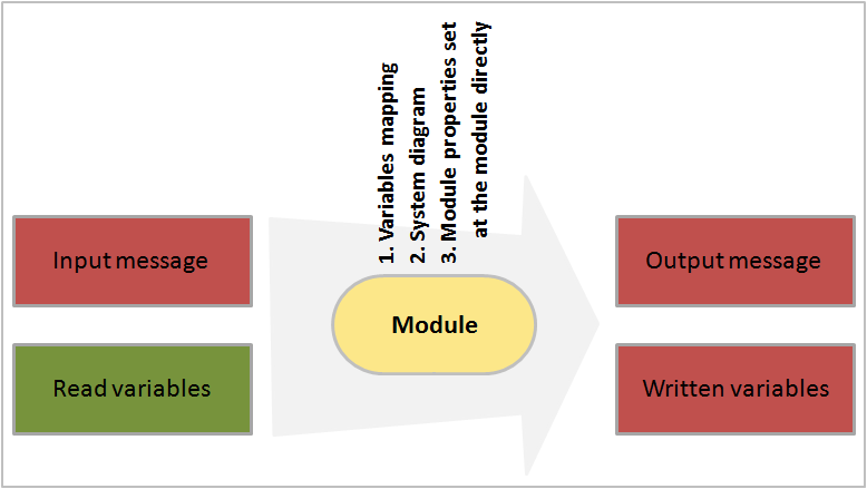
The processing result are an output message and variables (if applicable), which are handed over to the subsequent module.
Module Editor: User Interface
Call up
INUBIT Workbench > Module editor tab
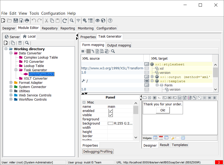
The module editor consists of two areas:
-
Server and local directories
The directories display modules that are stored either on the INUBIT Process Engine or on the local computer.
-
Properties tab/<module name> tab
-
Properties tab
Displays the properties of a module after it has been configured.
-
<Module name> tab
Depending on the module further configuration options are offered here.
-
Restrictions when working with the Module Editor
-
Publishing of modules is restricted if any module wizard is open on Server side. The Workflow that contains the module opened in the module wizard cannot be published. Other Workflows on the same level or in other Workflow groups can be published anyway.
-
If the module is being edited on the Local side, it cannot be renamed, published, or deleted.
-
If a module is opened using the wizard on the Local side in the Designer, it cannot be deleted on the Local side, but it can be deleted on Server side in the Designer.
-
A module opened on the Server side cannot be opened on the Local side.
-
A module opened on the Local side can be opened in view mode on the Server side, but it cannot be edited.
-
Data Converters — except FO Converter — cannot be opened multiple times.
Creating Modules
You have the following options for adding modules to an executable diagram (a Technical Workflow):
-
Drag and drop an existing module onto the workflow.
-
Create the module by adding via drag and drop or the context menu and then configure it.
Creating unconfigured modules
Proceed as follows
-
Display the Technical Workflow in your local directory.
-
In the sidebar, click the module group to which the required module belongs. The group is opened.
-
Click the required module then drag it onto the workspace. A dialog is displayed.
Refer to Dialog General Module Properties
-
Complete the fields and let the module wizard guide you through the module creation.
In Module Editor
Proceed as follows
-
In the INUBIT Workbench, display the Module Editor tab.
-
Open a module group folder and select the module type from which you want to create a new module.
-
Open the context menu, then select New. The module wizard opens and displays a dialog.
Refer to Dialog General Module Properties
-
Let the module wizard guide you through the remaining module configuration.
→ After the module has been created its name is displayed in the previously selected folder. You can now use the module in an executable diagram.
In Designer
Proceed as follows
-
Display the executable diagram in local mode.
-
Drag the required module onto the executable diagram’s workspace:
-
from the sidebar > docking window Modules:
-
If you drag a module-type folder onto the workspace, the module wizard for module creation is displayed. Let the wizard guide you through the configuration process; you can then use the module.
-
If you drag a configured module onto the workspace you can use it immediately.
-
-
from the sidebar > docking window Tools:
-
In the docking window, open the group the desired module is located in, for example:
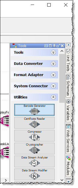
Drag the required module onto the workspace.
→ The module wizard opens and displays the dialog.
Refer to Dialog General Module Properties.
Let the module wizard guide you through the remaining module configuration.
-
-
Adding Configured Modules
Prerequisites
You have already created the modules.
Proceed as follows
-
Display the Technical Workflow in a local directory.
-
From the sidebar, open the docking window Links.
-
Navigate to the module which you want to add.
-
Drag the module onto the workspace.
→ The selected module appears as a symbol on the workspace. You can connect it to other modules in the workflow.
Displaying Module Properties
You can display a module’s properties without editing it.
Proceed as follows
-
In the Module Editor
-
In the Local tab: Double-click the module.
→ The properties tab is displayed.
-
-
In the Server tab:
-
Double-click the module. The properties tab is displayed.
-
Open the context menu and select Show properties.
→ The module wizard opens.
You can also display properties of other modules, open the Editor, and navigate through the tabs of the INUBIT Workbench. The module wizard is always displayed in the front.
-
-
In a workflow in the Designer
Display the diagram. Perform one of the following actions:
-
Double-click the module.
-
Open its context menu and select Show properties.
→ The module wizard opens.
-
Searching for Server-based Modules in the Tree Structure
In Technical Workflows you can let display for each module the corresponding server-based module in the tree structure of the Module Editor.
Proceed as follows
-
Display the Technical Workflows in the Designer > Server tab or in the Designer > Local tab.
-
Select the module for which you want to find the corresponding server-based module.
-
Open the context menu and select Show server module (in Module Editor).
→ In the Module Editor the Server tab is displayed. The corresponding module is highlighted.
Editing Module Properties
When editing a module, it is locked and thus protected against parallel editing by other users. The lock is canceled when publishing or deleting the module from the local directory.
Refer to Publishing Modules and Diagrams
|
You can change a module’s properties not only manually via the module’s wizard, but also dynamically during the module’s execution time. To achieve this, use the variables mapping. For an example, refer to Overwriting List Module Properties. |
Proceed as follows
-
In the Module Editor
-
In the Local tab
Select the module, open the context menu and select Edit properties. The module wizard is displayed.
-
In the Server tab
Select the module, open the context menu and select Edit.
-
-
From a diagram in the Designer
Display the diagram and do one of the following:
-
Press the Ctrl key while simultaneously double-clicking the module
-
Open its context menu then select Edit (in Module Editor).
→ The module is copied to a local directory and the module wizard is displayed.
-
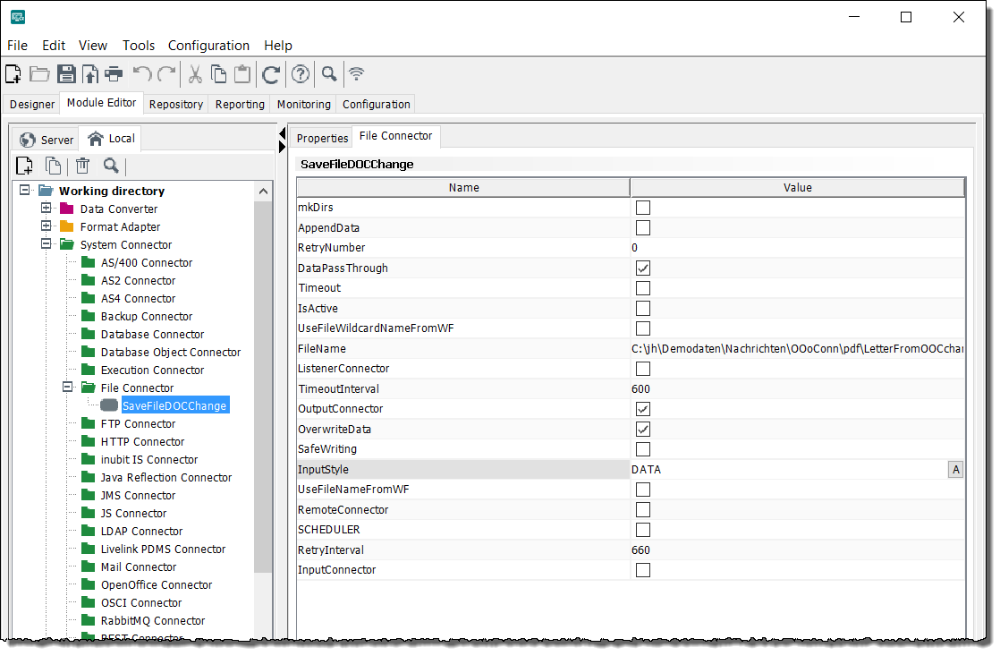
Editing Property Attributes
In case you want to change the attributes for filter settings, the property attributes can be opened and edited by clicking the A button.
Adding a Favorite Module
For easier access you can mark modules as favorites while editing diagrams in the Designer or working on modules in the Module Editor.
Proceed as follows
-
Choose a module.
-
In the Module Editor, navigate to the module which you want to add as favorite.
-
In the Designer:
-
Display your Technical Workflow in a local directory (refer to Editing Diagrams).
-
From the sidebar, open the docking window Modules.
-
Navigate to the module you want to add as favorite.
-
-
-
Right-click on the selected module to open the context menu and chose Add as favorite.
→ A confirmation window appears.
-
Confirm the prompt by clicking OK. Select Do not display this information again to avoid the prompt in the future.
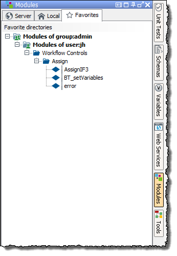
→ The module is accessible via the Favorites tab located in the Designer within the docking window Modules, which is displayed when you edit diagrams.
Removing a Favorite Module
Proceed as follows
-
Choose a module.
-
In the Module Editor, navigate to the module which you want to remove from favorites.
-
In the Designer:
-
Display your Technical Workflow in a local directory (refer to Editing Diagrams).
-
From the sidebar, open the docking window Modules.
-
Select a tab and navigate to the module you want to remove from favorites.
-
-
-
Right-click on the selected module to open the context menu and chose Remove from favorites.
→ A confirmation window appears.
-
Confirm the prompt by clicking OK. Select Do not display this information again to avoid the prompt in the future.
→ The module has been removed from the Favorites tab located in the Designer within the docking window Modules, which is displayed when you edit diagrams.
Adding Module Properties
For some modules, you can extend their functionality by adding properties.
For an application example see documentation of the utility INUBIT IS Configuration. Refer to Calculating the Size of Input Messages.
Proceed as follows
-
Open the module for editing. A tab named like the selected module is displayed.
-
In the View menu, activate the Properties editable option.
-
Open the context menu of the table and click Add. A dialog opens.
-
Enter the property name and select a data type.
-
Click OK to close the dialog. The new property is displayed in the properties table.
-
Define the property value.
-
Save your changes.
Connecting/Disconnecting Modules and Elements
The data or control flow between the individual elements or modules in a Technical Workflow is shown by the connections between the elements and/or modules.
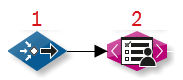
When connecting elements or modules the connection arrow always points to the element/module that you selected second:
Connecting
Proceed as follows
You have the following options for connecting elements or modules in diagrams:
-
Using the context menu
-
Select both elements.
-
Open the context menu then select Connect or Connect as error branch.
-
-
Using the mouse and keyboard
-
Click the first element.
-
Press and hold down the Shift key.
-
Drag the mouse pointer onto the second element.
-
→ The connection between the two elements selected is displayed.
Disconnecting
Proceed as follows
Select the connection. You have two options for disconnecting elements:
-
Press the Del key.
-
Open the context menu then select Disconnect.
→ The connection between the elements is deleted.
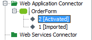
Activating System Connectors
The following conditions must be met so that system connectors in Technical Workflows are executed:
-
The system connectors must be active.
-
The diagram containing the system connectors must be active.
When you activate the diagram, all contained system connectors are also activated. Refer to Activating/Deactivating Diagrams.
-
The diagram containing the system connectors must be published on the INUBIT Process Engine.
Inactive system connectors are only executed when they are started manually, for example, for test or simulation purposes.
Proceed as follows
-
In the INUBIT Workbench, open the module editor.
-
Do one of the following:
-
Activating on the INUBIT Process Engine
-
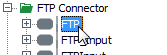
Display the system connectors that you want to activate in the server directories; for example:
-
From the context menu select Activate.
The system connector is activated, and the symbols now appear as follows:
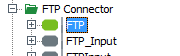
-
-
On activating, a new version of the system connector is created.
-
Activating locally
-
In the server directory display the system connector which you want to activate, for example
-
From the context menu, select Edit module. The wizard for editing the connector is displayed.
-
In the System connector properties dialog, select the Active option.
-
Refer to Connector status
Validating System Connectors
You can manually validate a System Connector module via the Validate button in the Module Editor.
|
When having opened more than one System Connector module for editing, only the System Connector module can be validated, which has been opened most recently. When trying to open another System Connector module, a corresponding warning message is displayed. To validate a System Connector module, which has not been opened last, you have to close all System Connector dialogs opened after the dialog of the System Connector module you want to validate. |
The validation returns missing properties and invalid configurations of a System Connector.
You can validate System Connectors while designing System Connector Templates locally.
|
If publishing a workflow diagram fails, use the System Connector validation for troubleshooting. |
Copying and Reusing Modules
When copying or reusing a module, the copy gets the same name and ID as the original, so you can reuse the same module in different contexts.
The copy of a System Connector module or Workflow Starter is automatically renamed when pasted into a diagram.
|
Settings on module connections, variable mapping and module versions are not copied! |
Copy and paste via the context menu of the module
-
Open the workflow that contains the module(s) to be copied.
-
Select the module(s) that you want to copy.
Hold the Ctrl key on your keyboard to select more modules.
-
Open the context menu and select Copy.
-
Open the workflow for editing in which you want to insert the copy.
-
Open the context menu and select Paste.
-
As same module
The pasted module will not be renamed. Changes in the properties of one module are reflected in the other module.
Not available for Tools, System Connector, and Workflow Starter. These modules and tools can only be pasted via As new module.
-
As new module
The pasted module will be renamed. Changes in the properties of one module have no effect on the other module.
The As same module and As new module options are available locally, for Technical Workflows only. The options are not available for cut-out modules.
-
Transfer modules from the sidebar docking window
-
Open the workflow into which the relevant module is to be inserted.
-
Open the Module docking window.
-
Select the module from the tab Server, Local or Favorites and apply it with one of the following variants:
-
Open the context menu of the module and click on Apply module.
-
Drag the module with the left mouse button into the diagram.
-
Finding Workflows in which a Module is Used
Proceed as follows
-
Display the Module Editor.
-
Select the module whose usage in workflows you wish to establish.
-
Open the context menu and select Show workflow > Server workflows or Show workflow > Local workflows.
→ The workflow is displayed in the Designer.
Finding and Deleting Unused Modules
Usage
You can search for unused modules in a selected server directory and delete all or only specific unused modules. Unused modules are not used in any diagram.
Proceed as follows
-
In the module editor, display the Server tab.
-
Select one of the following folder types in the Server tab:
-
Group folder
-
User folder
-
Module type folder
-
-
Open the context menu and choose Delete. → The Delete unused modules/version dialog is displayed.
-
Choose Modules in the Deletion Type section.
→ The unused modules are listed in the Select the modules section. If there are no unused modules in the selected directory, the list is empty.
-
Unselect all modules that are not to be deleted.
-
Click OK.
→ The dialog closes. The selected modules are deleted and subsequently will no longer be displayed in the module editor.
Deleting Module Versions
Usage
To improve the performance of the Process Engine, you can delete old module versions.
Proceed as follows
-
In the Module Editor, display the Server tab.
-
Select one of the following folders in the Server tab:
-
Group folder
-
User folder
-
Module type folder
-
-
Open the context menu and choose Delete. → The Delete unused modules/versions dialog is displayed.
-
Choose Versions in the Deletion Type section. → The modules of the selected directory are listed in the Select the modules section.
-
Unselect all modules whose older versions are not to be deleted.
-
In the Retain versions section, choose an option to specify which versions are not to be deleted.
-
Number of youngest versions
Enter a positive integer, for example
20, to indicate how many of the youngest versions, for example20, shall be retained. -
All younger versions including version
Enter a version number, for example
60. The version with the given number and all younger versions retain. -
All tagged versions
Only untagged versions are deleted.
-
All younger versions including
Enter a date and a time. The version(s) created on the given date and time as well as all younger versions retain.
-
-
Click OK. → The dialog closes. All versions of the selected modules being not specified in the Retain versions section are deleted and will no longer be displayed in the Module Editor.
|
Module versions linked with or without the technical workflow can be deleted. |
Importing Modules
You can import modules. The imported modules automatically become head versions. The version history and tags that might have been assigned are not imported with the module.
Proceed as follows
-
In the Module Editor, display the Server tab.
-
Select from the burger menu Import > Modules from the menu.
→ A dialog opens.
-
Click the
 icon next to the File field.
→ A file explorer is displayed.
-
Navigate to the directory in which the ZIP file containing the import modules is stored.
-
Select the ZIP file and click Open.
-
Select the user or user group into which the module is to be imported.
-
In the Import settings area, add a comment to enable traceability in the version information of a diagram.
-
Rename importing modules which are having the same name but different case
If this checkbox is checked, an imported non-system connector module is renamed by adding a hyphen and a consecutive number if a module with the same name already exists and if both names differ only by their spelling with uppercase/lowercase letters.
Otherwise, an importing module name is overwritten by the existing module name.
-
Click OK. The dialog closes.
→ The module is imported. The following rules apply:
-
If there are no modules with the same name in the selected group, the modules are imported without any changes.
-
If the selected user already has modules with the same name and if the Rename imported modules if they already exist with that name option is not set, the modules are imported as head version of the existing modules.
Refer to Versioning, Tagging, and Revision
-
If other users already have modules with the same name, the imported modules are renamed automatically.
-
In every case, an import protocol is displayed after the import.
Refer to Protocols
Exporting Modules
You can export modules as packed (*.zip) XML files in order to exchange them between different INUBIT installations and INUBIT versions.
During export, all referenced repository files are also automatically exported, e.g. referenced XML Schemas.
If paths and IDs change during a later import, because you import e.g. to another user, the references are automatically adapted.
Requirements
The modules must already have been published!
Proceed as follows
-
In the Module editor display the Server tab.
-
Perform one of the following actions:
-
Select one or several modules in a directory.
-
Select a module type folder, your user folder or a group folder.
-
Select the tag of the module version that you want to export, for example
-
-
Open the context menu and select Export.
→ An export wizard opens and guides you through the export.
Comparing Modules on Different Process Engines
Prerequisites
Both Process Engines are installed with an INUBIT version as of 8.0.
Proceed as follows
-
On the INUBIT Workbench, open the Module Editor tab.
-
Navigate to the module or to the directory for which you want to compare the modules containing in the directory and its subdirectories if any.
-
Open the context menu and choose the item Compare with another Process Engine.
-
Choose the tag you want to compare and click Next.
-
For comparison, enter the connection details for the remote process engine. Only the IP address or the DNS name of the remote system on which the Process Engine is running must be specified as the Server name.
-
If you select HTTPS as protocol, all necessary security settings must be made by clicking on the SSL… button.
If you enter incorrect details, the wizard page will display a corresponding message. You should correct your settings until the message disappears.
-
When all the settings are correct, click Next.
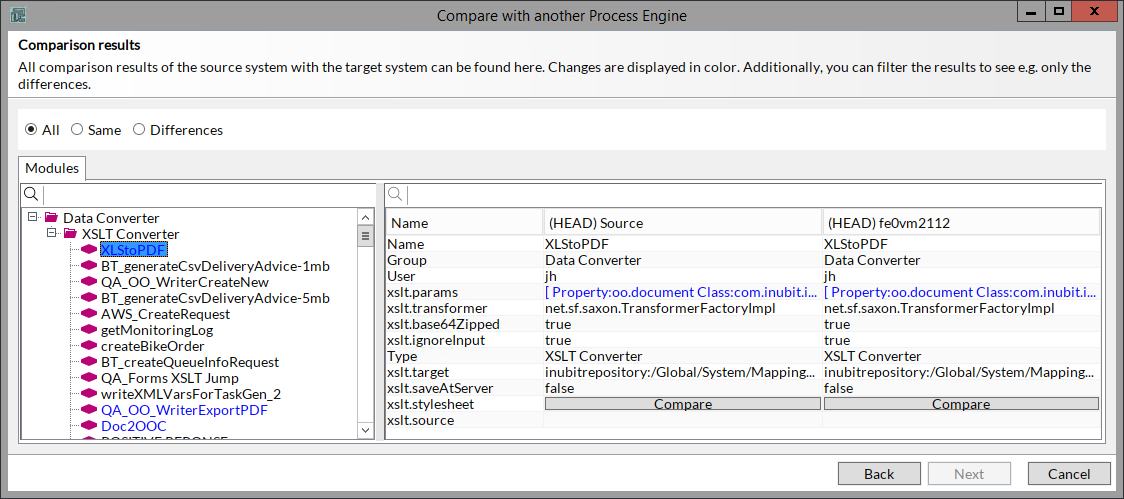
→ The Comparison results dialog is displayed.Differences between source modules and target modules are highlighted in color as follows:
-
Entry black: Entry is identical on both the source system and the target system.
-
Entry green: Entry is missing on the target system.
-
Entry red: Entry is missing on the source system.
-
Entry blue: Entry differs between source system and target system.
Additionally, you can filter the entries as follows:
-
All: depending on the Comparison result, all entries are highlighted in color.
-
Same: only entries that are identical on both systems are displayed.
-
Differences: only entries that differ on both systems are displayed.
-
-
To display the details, click the module name in the tree.
-
If the content of an XML structure differs, click on the Compare button to display the Document comparison.
On the bottom, the Differences window is displayed by default. Here, the differing lines are displayed detailing the differences.
By clicking the Differences button, you can hide/display the Differences window.
To display the Original document and/or the Compared document, click the corresponding button on the top left and on the top right, respectively.
-
Click OK to close the window.
Dialog General Module Properties
This dialog offers the following options:
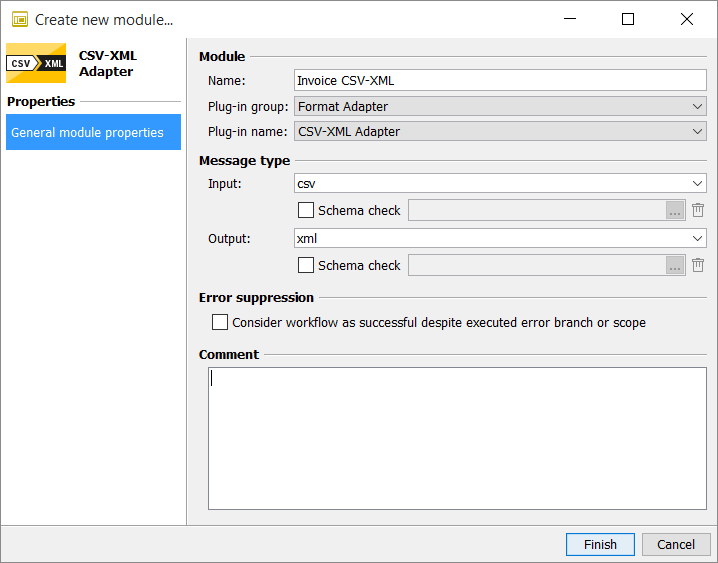
Module
-
Name: Enter any meaningful name. The module name must be unique on the INUBIT Process Engine. A corresponding message is produced if the name has already been taken.
Module names are not case-sensitive.
-
Plug-in group: The plug-in group is already pre-set to the correct value. To create a module from another plug-in group, select the group from the drop-down list.
-
Plug-in name: The plug-in name is already pre-set to the correct value. To create another plug-in, select it from the drop-down list.
Message type
-
Input/Output
Select the file type of the input or output message or enter it. File types are displayed next to the modules in the diagram to contribute to the readability of the diagram.
A message is produced if the message types at the previous/following modules do not match. You can still also use the modules with inappropriate message types without negative consequences for the workflow execution.
-
You can let XML based input and output messages validate against an XML Schema in order to check whether all elements exist, are provided in the expected order and have the correct data type. The XML Schema must be stored in the Repository.
For activating the check, mark the checkbox, then define the XML Schema.
The XML Schema is stored with the module and remains there, even if you deactivate the check. Click to cancel the assignment of the XML-Schema to the module.
In order that the schema check of a module is executed the schema check must also be activated for the workflow the module is used in.
Error suppression
-
Treat workflow as successful despite executed error branch or scope
-
Option not selected: The execution of a workflow is canceled if an error occurs at this module. The error branch or scope is activated.
-
Option selected: The normal error handling routines are not invoked, no entry is created in the queue manager and no e-mail notification is triggered.
You can also set the error suppression using the variables mapping by setting the module property
ErrorSuppression. Possible values aretrue(error suppression is active) andfalse(error suppression is inactive).The module property variable mapping overrides the module property checkbox when configured on the error branch.
-
Comment
The comment is optional.
All other dialogs involved in the creation of a module are module-specific.