Designer: Working with Diagrams
Overview
This section explains the basic steps involved in working with all diagram types. Functions only applicable to one diagram type are explained in the specific sections for that diagram type.
Quick start with tutorials
The tutorials offer a rapid introduction to the INUBIT software and to the following topics. Refer to:
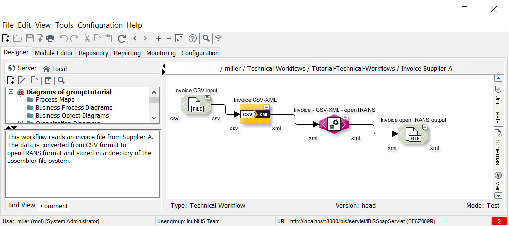
Designer: User Interface
Call up
INUBIT Workbench > Designer tab
In the Designer tab, all diagram types are managed which are contained within the functional scope of the INUBIT software and which are available for the current user according to her right configuration in the User Manager.
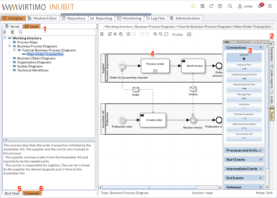
The Designer consists of the following areas:
-
Server and local directories
Display all diagrams that are visible to you on the INUBIT Process Engine and locally. The diagrams are organized hierarchically in directories with a separate directory being created for each user group and user.
In higher-level directories, as for example in the directory Tutorial-Business-Process-Diagrams a graphical overview over all diagrams and subdirectories contained in the higher-level directory is displayed. A click on a graphic displays the corresponding diagram or opens the subdirectory and its content.
-
Sidebar
The sidebar contains buttons opening the following docking windows:
-
Unit Tests
For creating and starting test cases.
Refer to Using Unit Tests
-
Schemas
To connect XML Schemas with Technical Workflows.
-
Variables
Displays all variables which are used in the currently displayed diagram.
Refer to
-
Web Services
Offers access to PartnerLinks, CorrelationSets, properties, and WSDLs.
Refer to Web Services
-
Templates
For using BPD templates in new diagrams.
Refer to Using BPD Templates
-
Link reports
(Displayed in local mode only when linking is possible)
For linking Business Process Diagrams with reports.
-
Links
(Displayed in local mode only when linkable diagrams are)
For accessing diagrams with which the currently displayed diagram can be linked.
-
Modules
(Displayed in local mode only)
Contains all diagrams which can be linked with the currently displayed diagram and all configured modules which can be used in the current diagram.
Refer to Copying and Reusing Modules
-
Tools
(Displayed in local mode only)
Contains all modules and elements which can be used in the displayed diagram type.
-
-
Docking window Links (open)
Sample for an open docking window.
-
Workspace
In the workspace, you assemble diagrams or diagram elements by drag and drop.
The background of the workspace tells in which directory you are working: in local directories, a gray grid is displayed in the background. The server working space has a white background.
-
Bird’s eye view of the diagram currently being displayed in the work area. You can click and move the blue-framed transparent rectangle to navigate to sections that are not currently visible in more complex diagrams.
-
Comment tab
Displays the comment of the currently selected or displayed diagram. The comment was entered when the diagram was created or edited.
Editing Diagrams
You can open one or multiple diagrams at the same time for editing.
Diagrams can only be edited in local directories. Thus, diagrams stored on the INUBIT Process Engine are copied to a local directory.
While a diagram is being edited, other users receive a warning message if they try to edit the same diagram.
Diagrams are released for editing by other users only after they have been published or deleted in the local directory.
Proceed as follows
-
Select one or more diagrams in the Server tab.
-
Open the context menu then select Edit diagram.
→ The diagrams are copied, the copies are moved into the appropriate local directory and displayed. You can now edit the diagrams.
Editing linked diagrams
For linked diagrams, you can selectively open a diagram in a local directory without unnecessarily having to open any other linked diagrams.
Proceed as follows
Double-click the link point while holding down the Ctrl key.
→ The linked diagram is opened for editing in a local directory and displayed.
Inserting elements
In many diagrams (e.g. in Business Process Diagrams, Business Object Diagrams, Organizational Diagrams and Technical Workflows) you can insert an element or module by dragging and dropping it on the connection line between two already existing elements or modules.
If it is syntactically correct to insert the selected element or module, the connection is highlighted in blue.
Deleting elements
If you delete an element from a diagram (e.g. from a Business Process Diagram or Technical Workflow), the resulting gap is closed automatically.
Locking and Unlocking Diagrams
Prerequisites
-
You have selected the checkbox Lock diagrams and modules for further editing on the Administration > General Settings > Administration > Diagrams tab.
-
If you want to unlock a diagram locked by another user, you need the right Unlock diagrams and modules currently edited by user.
Refer to Configure diagrams
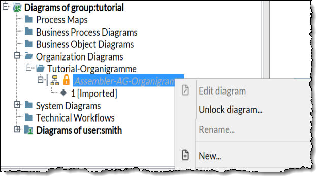
If you open one or more diagrams and/or modules for editing, they are locked automatically for other users, displayed as deactivated or grayed out, and with a padlock icon next to the diagram’s or module’s name. Other users can only view a locked diagram/module but cannot edit, rename, or delete it. At the top of the diagram view/module view in the work space, a message bar is displayed informing the user who has locked the diagram/module.
If a locked diagram or module needs to be unlocked, only a user is allowed to unlock it who has the right to unlock diagrams.
Proceed as follows
-
Log in to the workbench as a system administrator.
-
Open the Designer or the Module Editor.
-
Navigate to the diagram or module you want to unlock.
-
Open the context menu of the diagram or module and select the Unlock diagram item.
→ A confirmation window appears.
-
Confirm the prompt by clicking Yes or No, thus deciding whether you really want to unlock the diagram.
-
If you choose No, the diagram’s lock remains untouched.
-
If you choose Yes, the current user’s diagram lock is broken and another user can edit (and lock) it. The user whose lock has been broken is informed via instant message in the workbench that it is no longer possible to publish this diagram.
-
Activating/Deactivating Diagrams
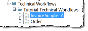
Executable diagrams such as Technical Workflows must be activated before they can be executed. Until the diagrams are activated they can only be started manually, for example, for test purposes.
As long as diagrams are not active, their diagram symbol is grayed out, e.g.:
A new diagram version is created each time the diagram is activated/deactivated!
|
You can only activate head diagram versions or versions with an active tag. If there is no active tag, the head version is executed automatically. |
The following functions are not available for deactivated diagrams:
-
Time-based starting by Scheduler
-
Event-based starting of the listener input connectors
-
Portlets for inactive Technical Workflow diagrams are not displayed in the portal.
Proceed as follows
-
In the INUBIT Workbench, display the Designer tab.
-
In the server mode, select all the diagrams that you want to activate. Alternatively, you can also select diagram directories in order to activate all diagrams contained in the directories.
-
Open the context menu and select Activate.
-
Only for Technical Workflows with deactivated system connectors: A dialog opens and lists all system connectors of the diagram. Select all system connectors which should be activated. Click Yes to start the activation.
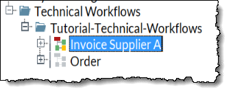
→ The diagrams are activated and the diagram symbols are represented in color:
Copying Diagrams
|
Diagrams can only be copied in the server directory. Note that versions of the diagrams are not copied! Refer to Versioning, Tagging, and Revision |
Proceed as follows
-
Select the diagram that you want to copy.
-
Open the context menu then select Copy. A dialog is displayed.
Refer to Diagram Tab - All Diagram Types
Enter a new name for the copy.
The name of a diagram must be unique on the INUBIT Process Engine!
-
Click on OK. The dialog window will close.
→ A check is made to see if the name is already in use. If the name is unique, the copy is created.
When copying a Technical Workflow, the modules contained in that Technical Workflow are also copied. Modules that are not re-usable, such as system connectors for example, are automatically renamed during the copy so that their names are also unique on the INUBIT Process Engine. This is done by adding a hyphen and number to the module names. You are notified when modules are renamed.
Unit tests of the workflow are not copied.
Moving Diagrams
You can move one or more diagrams from the same diagram folder, and complete diagram folders, between the users and user groups that are visible to you on the Designer tab.
|
You cannot move the user and user group folders and the supplied diagram type folders that they contain, such as Technical Workflows and Organization diagrams! |
Prerequisites
-
The diagrams are already published.
-
The elements and modules in the diagrams are only used in the diagrams to be moved.
Proceed as follows
-
Display the Designer > Server tab.
-
Select the diagrams or the diagram folder.
-
Open the context menu and choose Move. A dialog opens.
-
Select the diagram folder into which you want to move your diagrams or the diagram folder.
-
Choose OK to close the dialog.
→ The diagrams are moved and are displayed in the new position.
Validating Diagrams - Syntax Check
When modeling Business Process Diagrams, Business Object Diagrams, Technical Workflows and Organizational diagrams, you can use the validation to check the syntactic correctness of the diagrams.
The validation identifies incorrect elements/modules and reveals potential for optimization when modeling.
Proceed as follows
-
Open the diagram for editing.
-
In the toolbar, click the
 button.
If the diagram is valid, a corresponding message is displayed. If the diagram is not valid, the validation result is displayed below the working area in a docking window, e.g.
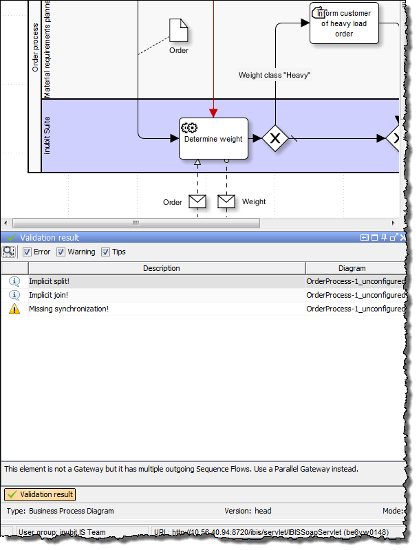
You can configure which results are to be displayed: e.g. to only display errors, you deactivate the Warning and Information options in the docking window.
To display the explanations for a message, click the corresponding message. At the same time, the defective module/ element is highlighted in color so that you can identify it quickly.
Checking Diagram Integrity
Users can check the integrity of their diagrams published.
|
Currently, the integrity check identifies missing or wrongly linked Repository files only. |
Proceed as follows
-
In the Designer, open the Server tab.
-
Select the diagram(s) to be verified.
You can check diagrams, diagram groups, users, user groups, and higher-level user group. User groups and higher-level user group are checked recursively. To select several diagrams keep the Ctrl key pressed while clicking the diagrams.
-
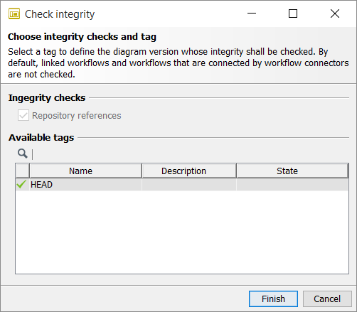
Open the context menu Check integrity for (one of) the selected diagram(s). A dialog appears.
-
If you don’t have licensed Versioning, click Finish to start the check.
-
If you have licensed Versioning, select a tag to define the diagram version, whose integrity shall be checked, and click Finish.
If Revision is activated (refer to Activating and Configuring Revision), only released tags can be selected.
-
→ If the integrity has been checked successfully, a corresponding message is displayed. If the integrity check has failed, all inconsistent workflows and/or modules are displayed. By selecting an entry, the element will be marked in the designer in background, and you can correct the error.
Structuring Workflows with Frames
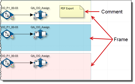
You can improve the readability of a diagram by grouping modules and elements related by content using frames. Grouped elements can be moved collectively.
Example
Proceed as follows
-
In the sidebar, click the Tools button. The docking window Tools is displayed.
-
Open the Tools area.
-
Drag the Frame element it the workspace and the modules which are to be grouped.
-
To name the frame and specify the position of the name, double-click it.
→ A dialog opens. Display the Element tab and enter the name. Specify the position in the Name alignment tab.
Commenting Diagrams, Modules, and Elements
You can add explanations or notes to diagrams and elements. Such comments help other users to become acquainted with the function of the diagram or elements.
Comments are displayed in the Comment tab, if you have selected a diagram in the directory tree resp. an element or module in the working area.
The image shows the comment to the middle frame, highlighted in red:
Additionally, you can add a Comment artifact to the diagram to describe certain sections of a diagram in detail.
Proceed as follows
-
Entering comments to a diagram or module
-
Select the diagram or module in a local directory.
-
Open the context menu and select Edit properties.
A dialog opens up: refer to Diagram Tab - All Diagram Types or refer to Dialog General Module Properties.
-
Enter your text in the Comment field.
-
-
Entering comments to an element
-
Double-click the element in the working space. The Element dialog opens.
-
Enter your text in the Comment field.
You can also enter HTML-formatted comments!
-
-
Adding a Comment artifact to a diagram
-
Select the diagram or module in a local directory.
-
Open the Tool docking window on the left.
-
Open the Artifact section.
-
Drag the Comment artifact to the desired position on the diagram.
-
Choose the desired text format: Plain text or HTML.
-
Enter the text.
When having chosen HTML, the text can be advanced formatted.
-
Editing Connections between Diagram Elements
You can assign a name to the connection between two elements, as for example frames, comments, activities, pools, roles or firewalls, and edit the displayed connection.
Proceed as follows
-
Select a connection line between two elements in your system diagram.
-
Open the context menu and select Edit. A dialog opens. In this dialog you can configure the connection as follows:
-
Naming the connection
-
Display the Element tab.
-
In order to assign a name to the connection, enter a name in Name field.
-
-
Changing the line type of the connection
-
Display the Line type tab
-
Select one line type and define, if lines shall be displayed with start arrow or end arrow.
-
-
Aligning Diagram Elements
You can align elements of all diagram types.
The following options are available:
-
Align to grid
The selected elements will be aligned to the predefined grid.
Refer to Changing INUBIT Workbench Settings
-
Align (left, right, top, bottom)
The selected elements will be aligned with the element that is furthest to the side you have chosen.
-
Center (horizontally, vertically)
The selected elements will be aligned to a horizontal or vertical axis that goes through their center.
-
Distribute (horizontally, vertically)
The minimum three selected elements will be distributed between the two outermost elements so there is the same space between the outside edges of the selected elements.
Proceed as follows
-
Select the elements that you want to align.
-
Right-click on one of the selected elements.
The element you have clicked will be used as the basis to align the other objects, excepting Align to grid and Distribute.
-
Choose Align entry from the context menu and then select the desired function.
Editing the Layout of Diagram Elements
You can adapt individually the layout of diagram elements as, for example, frames, comments, activities, pools, roles, firewalls, by changing the following aspects:
-
Background color, filling, color gradient
-
Frame color and type
-
Font size, style and color.
|
There aren’t all options available with all elements. |
Additional options are available in the diagram element context menu:
-
Save the changed layout of an element type as default layout, thus making it available for all users.
This option is available for users, who have the right to Designer > Save format as default on server.
Refer to Managing User Roles
-
Reset the layout of one or more elements back to default layout.
-
Reset back to shipping condition.
Proceed as follows
-
Open the diagram in a local directory.
-
Do one of the following:
-
Editing multiple elements in parallel
-
Select all elements whose layout should be changed.
-
Open the context menu and select Format > Edit. A dialog opens.
-
Display the Format tab.
-
-
Editing a single element
Double-click the element. The dialog for changing the formatting opens.
-
-
Changes the formatting.
-
Click OK to make the changes visible and to close the dialog.
End-to-end Navigation between Diagrams
Overview
Almost all different diagram types can be linked together. This offers the following advantages:
-
End-to-end navigation
You can navigate top-down via the relevant business process diagram to its technical implementation in a Technical Workflow. During full operation, the end-to-end navigation facilitates classification of occurring errors.
-
Modularization
You can underlay and link top-level processes with detailed sub-processes. The sub-processes are re-usable in different business process diagrams.
By way of practical introduction, refer to
Linking Diagrams
In order to link diagrams, you need a source and a target diagram:
-
Source diagram: The diagram in which the link is to be inserted. The source must be displayed in a local diagram so that it can be edited.
-
Target diagram: The diagram to which the link points. The target must be already published in a server directory.
Along with the link from the source diagram to the target diagram, a back link from the target diagram to the source diagram is created at the same time.
Link point
After linking, a link point is displayed in both diagrams, e.g.

On the link point, the icon of the target diagram type is always displayed.
Proceed as follows
-
Display the source diagram in local mode. The link directory displays the diagrams and modules on the INUBIT Process Engine.
-
From the sidebar open the docking window Links. In this window all diagrams in all server directories are listed, with which you can link the source diagram.
-
Navigate to your target diagram.
-
Drag the target diagram onto the element in the source diagram that is to be linked:
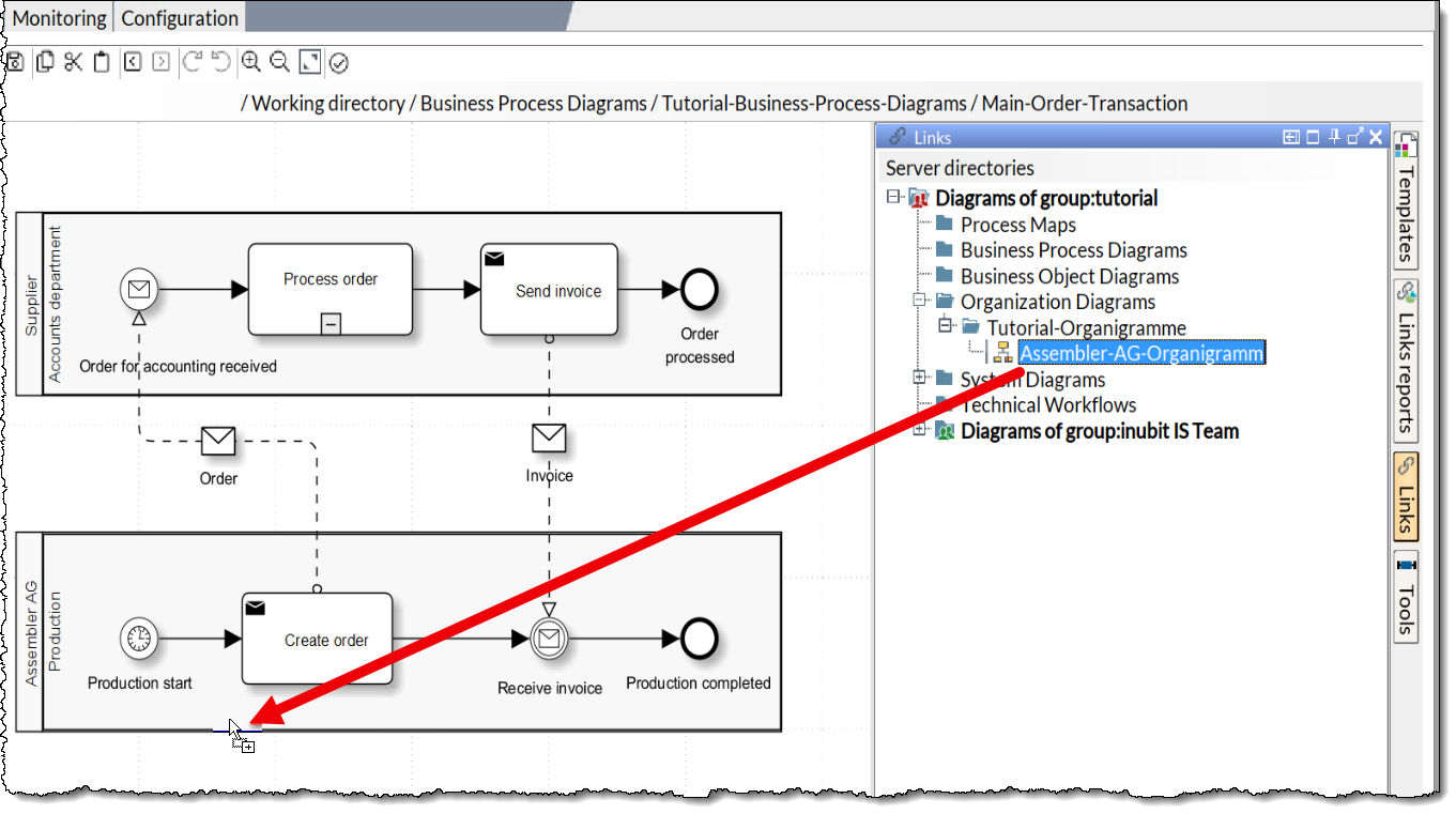
A dialog opens in which the target diagram is shown. Follow the instructions in this dialog. It depends on the diagram type and the selected element, if you can specifically link elements or entire diagrams.
-
Close the dialog by clicking OK. The dialog closes and in the selected element or diagram a link point is displayed.
-
Publish the source diagram. A link point is displayed in both diagrams.
|
The type of the link point depends on the linked diagram type. There are e.g. distinct link points for linked BPDs and linked Technical Workflows as well as a point that indicates that different diagram types are linked to the same element. If you work in the server mode, the context menu of a link point indicates with up or down arrows if you can jump to a target diagram (arrow down) or back to a source diagram (arrow up). Refer to Navigating between Linked Diagrams |
Navigating between Linked Diagrams
You can switch between source and target diagrams if these diagrams are already linked to each other.
Jump to local link target
Proceed as follows
If the link target is in the local directory, press the Ctrl key and double-click at the same time the link point:
Jump to server-based link target
Proceed as follows
If the link target is in the server directory, perform one of the following operations:
-
Double-click the link point.
-
Open the context menu of the link point and click the desired link, e.g.:
Editing Links
You can retrospectively change the target of a link to another element in the same diagram.
Proceed as follows
-
Open the diagram for editing.
-
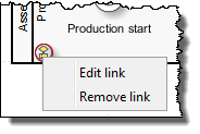
Open the context menu of the link point and select Edit link. A dialog opens in which the linked diagram is pictured.
-
Select the element to which your diagram is to be linked.
-
Click OK.
→ The dialog closes. The link has been changed.
Using Own Graphics as Symbols
You can insert any graphics into diagrams, e.g. in order to represent individual applications in system diagrams.
You can link these graphics to other diagram elements and append metadata to them.
Proceed as follows
-
Load the image into the Repository in the designated folder below Global > System > Diagram Images.
Refer to Storing Files in the Repository
-
Open the diagram, into which you want to insert the image, in a local folder.
-
In the sidebar click the Tools button to open the Tools docking window.
-
Open the area Tools.
-
Drag the element Image to the working area.
-
Open the element context menu and select Select image.
The Image Browser opens and shows all images available in the Repository for the selected diagram type.
-
Select the required graphic and click OK.
→ The dialog closes and the image is inserted.
Changing the Diagram Profile
A diagram profile defines the elements you can use for modeling diagrams. If you have a role with the right to use multiple diagram profiles, you can change between these profiles.
For information about creating diagram profiles refer to Diagram Profiles: Profiles for Modeling Elements.
Proceed as follows
-
Open the diagram for editing.
-
From the menu bar, select View > Profile > [Name_of_Profile].
→ In the Tools docking window, the number of displayed modeling elements changes.
Deleting Diagrams/Diagram Groups
You can delete an individual diagram, multiple diagrams or diagram groups.
|
Diagrams cannot be deleted when a module wizard window is open. |
Proceed as follows
-
In the INUBIT Workbench, display the Designer tab.
-
In the server or local directory, select one or more diagrams or the diagram group that you want to delete. To select multiple diagrams at the same time, keep the Ctrl key pressed.
If a diagram exists in both the server directory and a local directory, you must delete both diagrams individually.
-
Open the context menu and select Delete.
→ The Delete diagrams/versions dialog is displayed.
-
Choose Diagrams in the Deletion Type section.
→ The diagrams of the selected directory are listed in the Select the diagrams section.
-
Unselect all diagrams that are not to be deleted.
-
Activate the checkbox Including the modules that are not used in other diagrams to delete the modules that are not used in other diagrams as well.
-
Click OK to delete the diagrams/diagram groups and modules if chosen.
→ The diagram or diagram group together with its versions and — if chosen — the modules that are not used in other diagrams are deleted.
Deleting Diagram Versions
Usage
To improve the performance of the Process Engine, you can delete old diagram versions.
Proceed as follows
-
In the Designer, display the Server tab.
-
Select one of the following folders in the Server tab:
-
Group folder
-
User folder
-
Module type folder
-
-
Open the context menu and choose Delete.
→ The Delete diagrams/versions dialog is displayed.
-
Choose Versions in the Deletion Type section.
→ The diagrams of the selected directory are listed in the Select the diagrams section.
-
Unselect all diagrams whose older versions are not to be deleted.
-
In the Retain versions section, choose an option to specify which versions are not to be deleted.
-
Number of youngest versions
Enter a positive integer, for example
20, to indicate how many of the youngest versions, for example20, shall be retained. -
All younger versions including version
Enter a version number, for example 6`0`. The version with the given number and all younger versions retain.
-
All tagged versions
Only untagged versions are deleted.
-
All younger versions including
Enter a date and a time. The version(s) created on the given date and time as well as all younger versions retain.
-
-
Click OK.
→ The dialog closes. All versions of the selected diagrams being not specified in the Retain versions section are deleted and will no longer be displayed in the Designer.
Importing Diagrams
You can import all diagram types either individually or in groups. Version histories or tags are not imported.
However, you can enter, choose, or create a tag and assign it to all diagrams using the Apply tag(s) field.
If no tag is set, imported diagrams automatically become head versions.
-
Import
-
To import a Diagram in several formats, e.g., BPNM, ARIS, Bonapart, or XPDL, a Diagram group, or Diagram texts.
Refer to
-
To import Modules or Task texts, refer to Importing Modules.
-
Proceed as follows
-
Display the Designer tab.
-
From the Burger menu, select Import > INUBIT diagram (group).
→ A dialog is displayed.
-
Click
 to the right of the File field to load the import file.
→ A file explorer is displayed.
-
Navigate to the directory in which the import file you want to import is stored.
-
Select the diagram.
-
Click Open.
-
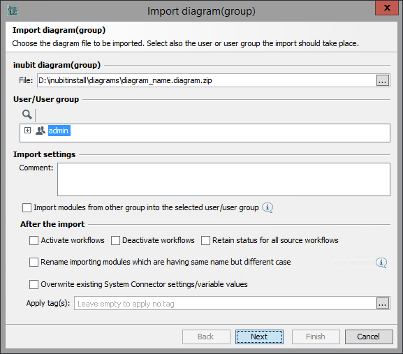
In the User/User group area, select the user or user group into which the diagram is to be imported.
-
In the Import settings area, add a comment to enable traceability in the version information of a diagram.
-
If, when importing, you select a user or a user group different from that defined in the import file, you can select whether the workflows and modules should be imported into the selected user or user group or into the same user/ user group as defined during the export:
-
To import the workflows and modules into the currently selected user/user group, select the Import modules from other group into selected user/user group option.
This option is especially useful if you import a workflow with modules that belonged to a group A being a higher-level group to the group B you have currently selected and is invisible for the currently selected group.
-
If you do not select the option, the modules are imported into the same user or user group that was defined during the export.
-
-
In the After the import section, decide whether the workflow and the related modules will be activated, deactivated, or retain the status of the source workflows after import.
If neither of the options Activate workflows or Deactivate workflows is selected, the import state depends on the following properties:
-
If the workflow already exists in the target system, the state of this workflow will be adopted.
-
If the workflow does not exist in the target system, the default state of the workflow will be deactivated.
If the Retain status of the source workflows option is set, the imported workflows get the same status as the source workflow had at the time of their export.
-
-
Rename importing modules which are having the same name but different case
If this checkbox is checked, an importing non-system connector module is renamed by adding a hyphen and a consecutive number if a module with the same name already exists and if both names differ only by their spelling with uppercase/lowercase letters.
Otherwise, an importing module name is overwritten by the existing module name.
-
Overwriting existing System Connector settings/variable values
If the import diagram contains system connectors and/or variables that already exist on your system, you must specify what is to be done with the already existing values:
-
To overwrite all existing values, select the option Overwrite existing System Connector settings/variable values.
-
If the existing values are to be retained, or if you want to overwrite only some existing values, do not select the option. The values are displayed in the next dialog, and you can adjust them manually if you wish to.
-
In system diagrams, the existing resource setting will not be overwritten if the option is not selected. You can see the difference between the target system values and import file, but not edit them. The screen shows only the difference.
You can define the properties that are to be configurable during import/deployment in the deployment configuration, refer to Configuring Module and System Connector Deployment.
When importing a technical workflow that contains a global variable that already exists, the global variable is handled as follows:
-
If both name and type of the global variables match, the existing variable is used. If both of the global variables are also having a constant value, the global variable is handled as follows:
-
If the constant values match, the existing global variable is used.
-
If the constant values do not match, a renamed global variable is created.
-
-
If the names of the global variables match but not their types, a renamed global variable is created.
-
-
Apply Tag(s)
To apply a tag to all diagrams being imported, enter an existing tag or click the Choose tag(s) icon
to select a tag or create a new one in the Create or Set tag dialog.
Separate multiple tags by semicolons. -
Click Finish.
-
If you have defined that the already existing settings are to be preserved, another dialog is displayed. In this dialog, you can change the module properties of the system connectors and the variables. The color-coding has the following meaning:
-
Black: The property is present on the target system with the same values.
-
Green: The property is not yet present on the target system.
-
Blue: The property is present on the target system with different values.
Adjust the settings as you wish, then click OK.
-
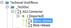
The diagram is imported. The following rules apply:
-
If the selected group does not yet contain a diagram with the same name, the diagram is imported with the name unchanged.
-
If a diagram with the same name is present for the selected user, the diagram is imported as the head version of the existing diagram.
-
If a diagram with the same name is already present for another user, the name of the imported diagram is automatically changed (
-1added). -
Regarding the modules contained in the diagrams, refer to Importing Modules.
After the import, an import protocol is displayed.
Refer to Protocols
Importing Technical Workflows and Users/User Groups automatically
Usage
Importing Technical Workflows and Users/User Groups automatically at server start-up
Proceed as follows
-
Export the Technical Workflows or Users/User Groups as ZIP archive.
-
Store the Technical Workflows or Users/User Groups to be imported as ZIP archive in the following directory:
<SUITE-INSTALL-DIR>/inubit/server/ibis_root/conf/autoimport/{workflow|user}/<user name>You can import Technical Workflows into one or more users. To do this, create a separate directory for each user and store the respective Technical Workflows into the user’s directory.
-
When the Process Engine is restarted, all directories below the
<SUITE-INSTALL-DIR>/inubit/server/ibis_root/conf/autoimport/directory are read, imported, and added to the user configured via the user’s directory.
Importing Process Models with Other Formats
You can import process models that are in the following formats:
-
ARIS 6/7 eEPC as BPD
-
Bonapart
-
XPDL diagrams.
Proceed as follows
-
In the INUBIT Workbench, display the Designer tab.
-
From the Burger menu, select Import and the format to be imported.
Importing ARIS models: Refer to ARIS Model Import - Mapping Table eEPC/BPD.
A wizard opens for selecting the import file.
-
Click
.
A file explorer opens. -
Navigate to the file and click Open. The file name is displayed in the File field.
-
Click Next. Another page is displayed.
-
Select the user/user group the file is to be imported to.
-
Click Finish.
→ The file is imported and displayed in the Server tab of the Designer. After the import an import protocol is displayed.
Refer to Protocols
Export diagrams
You can export all diagram types individually or in groups using the context menu on the tree structure in the "Designer" tab. Different export formats are supported:
-
INUBIT diagram(group)
-
BPMN
Refer to Exporting/Importing Diagrams as BPMN
-
Graphic
Refer to Exporting a Diagram as Image
-
XPDL
Refer to Exporting XPDL
-
Diagram texts
To export Modules or Task texts
Refer to Exporting Modules.
Exporting/Importing Diagrams as XPDL
Usage
Export/import Business Process Diagrams (BPD) as XPDL 2.1 or XPDL 2.2.
Refer to https://en.wikipedia.org/wiki/XPDL.
There are templates with the corresponding settings for some systems:
-
INUBIT
-
Adonis
-
BizAgi
-
ITP-Commerce
-
SemTalk
-
TIBCO
Exporting XPDL
Proceed as follows
-
Select the BPD to be exported in the server directory.
-
In the Burger menu, open Export > XPDL.
-
Select the tag to be exported.
-
Enter the path and the file name for the export file or navigate there by clicking the
icon. -
Choose the desired BPMN tool you want to export the diagram to in the Settings window. The settings are preset correctly. Additional settings are possible. If the list does not contain the desired tool, set the options manually based on the requirements of the tool.
-
Set the required options in the Settings, Lane position, Element position, and Number of processes sections.
-
Click Finish to store the BPD.
Importing XPDL
Proceed as follows
-
In the Burger menu, open Import > XPDL diagram.
-
Enter the path and the file name of the import file or navigate there by clicking the
icon. -
Select the user/user group for the diagram to be imported.
-
Select the BPMN tool which diagram to be imported in the Settings window. The settings are preset correctly. Additional settings are possible. If the list does not contain the desired tool set the options manually based on the requirements of the tool.
-
Set the required options in the Settings, Lane position, Element position, and Number of processes sections.
-
Click Finish to start the import.
-
Confirm the import protocol by clicking OK.
Exporting/Importing Diagrams as BPMN
You can export and import Business Process Diagrams as a BPMN 2.0-DI standard (file type: .bpmn).
|
Message artifacts where Initiating has been deselected must be checked, as this does not represent a BPMN attribute. Choreography Task and Call Choreography Activity elements are not differentiated in BPMN. |
Export Diagram
-
In the workbench, select the published diagram.
-
In the Burger menu, go to Export > BPMN.
-
In the following dialog, select the tag to be exported and specify the file path.
|
Events with different event definitions are adopted as default elements. Image and Black Box Pool elements are not supported by BPMN and will not be exported. If a diagram has been imported containing a Lane without Pool, it can be exported as it has been imported. |
Import Diagram
-
In the burger menu, go to Import > BPMN diagram.
-
In the following dialog, enter the path of the file to be imported and select the user or user group.
In the Protocols dialog, you can save import information as XML or load already created protocols.
|
Exporting Diagrams and Tagged Versions as Compressed XML File
For exchanging one or more diagrams between different installations and INUBIT versions, you can export them as compressed (*.zip) XML files.
During export, all Repository files referenced in the diagram are automatically referenced, too, e.g. referenced XML Schemas or graphics from the Repository. If paths or IDs change during a later import, e.g. because another user is imported, the references are automatically adapted.
If you use Tagging, you define while exporting whether the head version or any other version is to be exported.
Prerequisites
You have displayed the Designer > Server tab.
Exporting a single diagram (head or tagged version)
Proceed as follows
-
Select the diagram.
-
Open the context menu and select Export.
-
Only when using tagging:
The export wizard for selecting a tag opens. Select a tag and click Finish. The wizard closes.A file explorer opens.
-
-
Navigate to the directory you want to save the export file to. The name is proposed according to the following pattern
diagramname.module.zip. -
Click Save.
Alternatively do the following
-
Display the diagram.
-
From the menu bar, select Edit > Export > INUBIT diagram.
A file explorer opens.
-
Navigate to the directory you want to save the export file to. The name is proposed according to the following pattern
diagramname.module.zip. -
Click Save.
Exporting several diagrams (head or tagged version)
-
Select your diagram, user or group folder. You can also select several single diagrams in different folders by keeping the ctrl key pressed while selecting.
-
Open the context menu and select Export.
-
Only when using tagging:
The export wizard for selecting a tag opens. Select a tag and click Finish. The dialog closes.
A file explorer opens.
-
Navigate to the directory you want to save the export file to. The name is proposed according to the following pattern
diagramname.module.zip. -
Click Save.
Exporting tagged diagram versions directly
-
Select the tag of the diagram version, which you want to export, for example:
-
Open the context menu and select Export.
-
The export wizard opens. Specify if linked diagrams and workflows which are connected by Workflow Connectors and Unit Tests are to be exported.
-
Click Finish to close the wizard.
A file explorer opens.
-
Navigate to the directory you want to save the export file to. The name is proposed according to the following pattern
diagramname.module.zip. -
Click Save.
→ You are prompted to specify where you want to store the export file and to provide a name for it. The file is then exported to the specified directory.
Exporting a Diagram as Image or PDF
You can create screenshots of diagrams in Designer’s work area and store them in PNG format, in PDF format, and in EMF format to the clipboard. The current display size of the diagram is always retained.
Saving a Diagram as Image File
Proceed as follows
-
Display the diagram in the Server or Local tab.
-
From the burger menu, select Export > Graphic. A file explorer opens.
-
Select the desired file format (EMF, JPG, or PNG).
-
Navigate to the desired location for storing and click Save.
→ The diagram is saved as image file.
Saving a Diagram as PDF File
Proceed as follows
-
Display the diagram in the Server or Local tab.
-
From the burger menu, select Export > PDF. A file explorer opens.
-
Navigate to the desired location for storing and click Save.
→ The diagram is saved as *.pdf file.
Copying a Diagram to the Clipboard in EMF format
Proceed as follows
-
Display the diagram in the Server or Local tab.
-
From the burger menu, select Export > EMF image to the clipboard.
→ The diagram is saved in EMF format to the clipboard. Afterward, you can paste the image into a Microsoft Office file.
Comparing Technical Workflow Diagrams on Different Process Engines
Prerequisites
Both Process Engines are installed with an INUBIT version as of 8.0.
Proceed as follows
-
On the INUBIT Workbench, open the Designer tab.
-
Navigate to the Technical Workflow directory for which you want to compare the diagrams containing in the directory and its subdirectories if any.
-
Open the context menu and choose the item Compare with another Process Engine.
-
Choose the tag you want to compare and click Next.
-
For comparison, enter the connection details for the remote process engine. Only the IP address or the DNS name of the remote system on which the Process Engine is running must be specified as the Server name.
-
If you select HTTPS as protocol, all necessary security settings must be made by clicking on the SSL… button.
If you enter incorrect details, the wizard page will display a corresponding message. You should correct your settings until the message disappears.
-
When all the settings are correct, click Next.
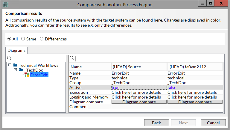
→ The Comparison results dialog is displayed.Differences between source diagram and target diagram are highlighted in color as follows:
-
Entry black: file is identical on both the source system and the target system.
-
Entry green: file is missing on the target system.
-
Entry red: file is missing on the source system.
-
Entry blue: file differs between source system and target system.
Additionally, you can filter the Entries as follows:
-
All: depending on the Comparison result, all entries are highlighted in color.
-
Same: only entries that are identical on both systems are displayed.
-
Differences: only entries that differ on both systems are displayed.
-
-
To display the details, click the diagram name in the tree.
-
If the diagrams differ, click on the Compare button to display the Diagram compare.
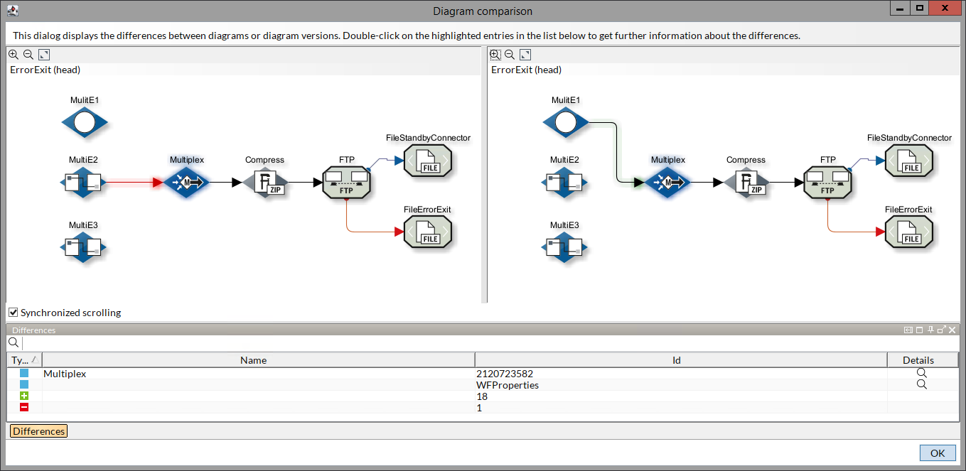
On the bottom, the Differences window is displayed by default. Here, the differing lines are displayed detailing the differences.
By clicking the Differences button, you can hide/display the Differences window.
To display the diagram element, click the entry in the Differences window.
To display further details of the diagram element, double-click the entry in the Differences window.
-
Click OK to close the window.
Internationalization: Maintaining Multi-Lingual Texts
You can create, maintain, display and export labels in reports, comments on diagrams and elements as well as names of elements and Ad hoc process starters in more than one language (in addition to the default language).
Configuring Other Languages
Before texts can be entered in other languages you must define these languages.
Proceed as follows
-
In the INUBIT Workbench, display the Administration > General Settings tab.
-
Open the Administration > Miscellaneous configuration area.
-
Next to the Additional languages option, click the
button.
A dialog is displayed. -
Select the checkboxes for all the languages you want to use.
-
Click OK. The dialog closes.
-
Save your changes.
→ You can now enter comments in the selected languages.
Removing Languages
In order to remove languages, you must remove them from the selection of languages.
Refer to Configuring Other Languages
If there still are texts in one of the removed languages, then these texts will continue to be displayed. In the configuration dialog an exclamation mark next to the name of the language signalizes, that the language is not configured anymore, for example:
To remove tabs with exclamation marks, simply delete the texts contained in these tabs.
Adding Multi-Lingual Texts
You can enter texts in other languages directly at diagrams, elements or reports.
Prerequisites
Additional languages are configured.
Refer to Configuring Other Languages
Proceed as follows
-
Display one of the following dialogs:
-
Diagram comments: refer to Diagram Tab - All Diagram Types
-
Labels and texts in reports: refer to Reporting Dialog General
-
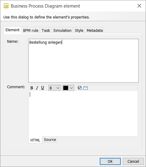
Business Process Diagram element, for example
-
or another element like frames or comments.
-
-
In the top right corner of the input field click
 .
A dialog opens up.
For each language a separate tab is displayed.
.
A dialog opens up.
For each language a separate tab is displayed. -
Enter your texts.
-
Click OK to close the dialog and to store the texts.
Displaying Multi-Lingual Texts in INUBIT Workbench and BPC Portal
Multi-lingual diagram texts are displayed in the INUBIT Workbench as well as in the BPC Portal.
Prerequisites
-
Additional languages are already defined.
Refer to Configuring Other Languages
-
Texts in additional languages are already entered.
Refer to Adding Multi-Lingual Texts
Displaying multi-lingual texts in the INUBIT Workbench
To check translated texts within their contexts, switch the language for diagrams in the INUBIT Workbench.
Proceed as follows
In the INUBIT Workbench, select from the User Menu Language in Diagrams > [Name of the language].
Displaying multi-lingual texts in the BPC Portal
In the Portal, diagram texts are displayed automatically in the language of the currently logged-in user.
Exporting/Importing Multi-Lingual Texts for Translations
In order to let texts in comments and elements of Business Process Diagrams translate comfortably into one or more languages, you can export texts into an Excel file and import them after the translation.
Proceed as follows
-
In the INUBIT Workbench display the Designer > Server tab.
-
From the burger menu select Export > Diagram texts.
→ A wizard for selecting diagrams opens up and guides you through the export.
For detailed information about the structure of the Excel file and importing the texts refer to Exporting and Importing Form Texts for Translation.
Auto-aligning Diagrams
You can have your diagrams automatically adjusted. For this, you can use the auto-layout function in order to optimally align all elements contained in you diagram. For this, you can use the auto-layout function in order to optimally align all elements contained in you diagram.
Prerequisites
The auto-layout function is activated.
Refer to Burger Menu.
Proceed as follows
-
In the Designer tab, display the diagram that you want to align.
-
In the toolbar, click the
 button.
→ The objects in the diagram are automatically aligned.
|
Due to a diagram’s complexity, the auto-aligning might produce insufficient results. In this case, you can reverse the auto-aligning by pressing Ctrl+z. |
Diagram language
-
Language in diagrams/reports
Diagrams and reports in the INUBIT Workbench can be displayed in different languages, refer to Internationalization: Defining Languages for Diagrams.
-
Show module names/Show module version/Show module numbers
Checkboxes to display or hide the module names, module versions, and/or the module IDs next to the module icon.
These options are visible only if you have selected a workflow in the Designer. To search for a module name or module ID press Ctrl+F in the workflow’s working area.
Dialog Description: Diagram Properties
The diagram properties wizard is used to create and edit a diagram. It consists of the following tabs.
Refer to:
You can find explanations of the various diagram types in the related sections.
Refer to:
Diagram Tab - All Diagram Types
-
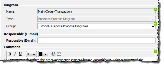
Name
Name of the diagram. The default name must be unique among the diagrams already present in both the local and the server directory. For all the other languages, you can enter an arbitrary description.
To enter details in other languages click the plus symbol in the right upper corner of the Name field:
The dialog for entering multi-lingual details is displayed only if more languages than only the default language were defined.
Refer to Configuring Other Languages
-
Type
The diagram type is already correctly preset.
-
Group
Select the group in which the diagram is to be stored, or enter a new group name. The group is then automatically created. Group names can be multilingual.
-
Responsible (E-Mail)
Enter the e-mail address of the person responsible for the diagram who should get an e-mail message in case the notification of change for linked diagrams is activated.
-
Comment
You can add comments on the diagram, for example to document its task. Comments can be multilingual. Diagram comments are displayed in Designer’s comments area and (for non-executable diagrams) in the BPC Portal.
Refer to
To create the comment you can
-
enter HTML source text in the Source tab
-
use the HTML editor in the HTML tab
An easy way to input hyperlinks or mailto links is to select the text to be clickable, click
 (URL) or
  (e-mail) then complete the fields in the dialog that is displayed.
-
Business Object Diagram Tab - BOD Only
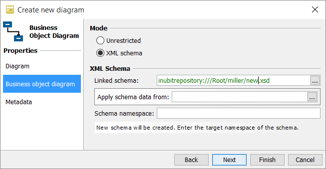
Mode
-
Unrestricted
For creating a UML class diagram.
Refer to UML Modeling Elements in BO Diagrams
-
XML schema
For creating a UML class diagram which is linked to an XML Schema.
Refer to
Execution Tab - TWF Only
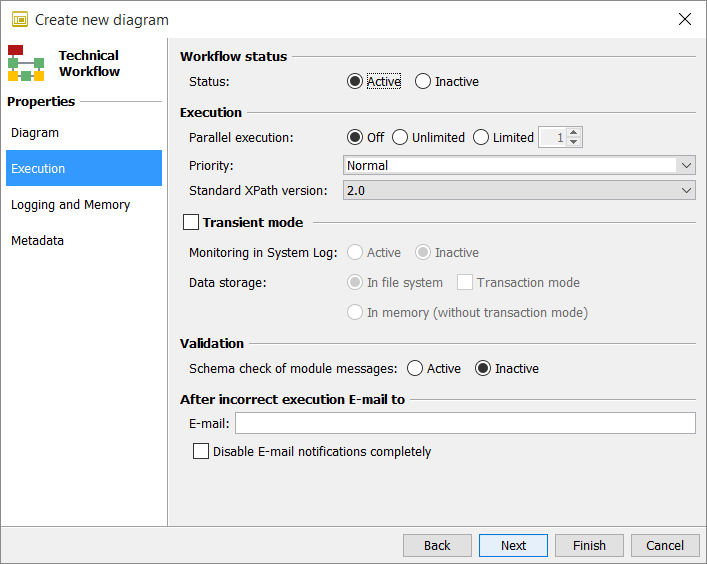
Workflow status
-
Status
Executable diagrams like Technical Workflows must be activated before they can be executed. As long as diagrams are deactivated, you can only start them manually.
Refer to Activating/Deactivating Diagrams
Execution
-
Privileged execution by separate workflow threads
Check this checkbox to mark this workflow as privileged workflow. Hence, this workflow can use the configured number of reserved workflow threads.
This checkbox is only visible if you have specified the field Reserved threads for privileged workflows in % (Workbench > Configuration > General Settings > Administration > Threads) to a value greater than 0, and you have restarted the Process Engine afterward.
-
Parallel execution
Each time an executable diagram is started, a process is created. You can define the number of processes that can run in parallel.
Ensure that processes executed in parallel do not mutually block each other. If this does happen, however, the blockade must not lead to inconsistencies, as it is the case, for example, when using database connections or when retrieving messages from other systems. Parallel execution is risk-free, for example, if workflows simply convert messages without accessing the file system.
-
Off: Default.
There are no parallel processes, the next process has to wait for the end of the preceding process.
Unlimited: There are no diagram-specific restrictions. Because for each process a workflow thread is needed, your specification here may be restricted by the maximum number of parallel threads defined in your license and by the configuration of the workflow thread pool of the INUBIT software.
Limited: The specified number of instances is executed in parallel. Because for each process a workflow thread is needed, your specification here may be restricted by the maximum number of parallel threads defined in your license and by the configuration of the workflow thread pool of the INUBIT software.
-
-
Priority
Specify whether the diagram is to have priority of execution. The following rules apply:
-
Diagrams with priority level Normal share system resources on an equal footing with all other diagrams with the same priority.
-
Diagrams with priority level Lowest go to the back of the queue for system resources to allow diagrams with a higher priority level to be executed.
-
Diagrams with priority level Highest have priority access to system resources. All diagrams with lower priority levels are held back until the execution of diagrams with higher priority has ended.
-
-
Standard XPath version
For defining the XPath range of functions concerning the variables mapping and all modules in the diagram, in which XPath is used (as for example Demultiplexer, If, Switch and Wait modules).
XPath 1.0 is deprecated, and it is not supported as of INUBIT 8.0. Hence, it is recommended to not use XPath 1.0.
This option does not affect the XPath functions in the XSLT Converter!
Transient mode
The transient mode accelerates the execution of processes. To achieve this, you can turn off the System Log and the transaction mode.
|
After server shutdowns, the transient mode may lead to inconsistent states because long-running transactions cannot be executed further and canceled transactions cannot be undone. Only use this option for diagrams that must be executed quickly but which do not give rise to inconsistencies in the system should they be blocked or canceled. |
-
Monitoring in System Log
If Inactive is selected, the monitoring in the System Log is deactivated.
-
Data storage
As a default, data and variables are stored in the file system. If In memory (without transaction mode) is activated, the data and variables are kept in the working memory, if possible.
If the workflow is not in transient mode, other nodes can resume the interrupted process, when the node (where the process was running originally) shuts down.
-
Transaction mode
-
If activated, after a shutdown of the INUBIT Process Engine the workflows are continued at exactly the same module where they have been interrupted.
-
If deactivated, the workflows interrupted after a shutdown are not continued.
-
If you have selected Data storage In memory (without transaction mode) you cannot activate the transaction mode!
Validation
-
Schema check of module messages
For activating/deactivating the schema check at the modules in the diagram.
Refer to Schema validation
After incorrect execution e-mail to
-
E-mail
E-mail address of the person to be informed after a faulty execution. The sender of the e-mail is shown as the e-mail address that was created for user root. The e-mail contains the following information:
-
Server: Name and IP-address of the server
-
Date: Date and time of the errors
-
Workflow: Name of the faulty workflow
-
Process-ID: Process-ID of the faulty workflow
-
Module: Name and number of the faulty module
-
Error: Text describing the error
For e-mails to be sent, the e-mail notification system must be activated.
Refer to Alerting
-
If no e-mail address is specified here, user root with role System administrator is notified.
-
Disable e-mail notifications completely
When activated, no e-mails are sent following a faulty execution of the diagram.
Refer to
Logging and Memory Tab - TWF Only
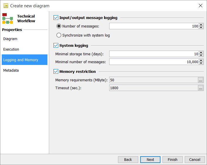
Input/output message logging
|
Only activate Input/output message logging for debugging purposes or for analyzing errors. Otherwise, performance losses can quickly occur depending on the scope of use on systems under load. To save both the input message and the error messages only in case of an error, use the error branch of a module or of a Scope, refer to Handling and Suppressing Errors. |
When input/output message logging is activated, the incoming and outgoing messages are stored from the workflow’s system connectors.
This is useful, for example, when a workflow has executed incorrectly and needs to be re-started with the same incoming messages. You re-start the workflows via the Queue Manager and the System Log. There, you can also display the input and output messages.
Refer to
|
If input/output logging is activated additionally for one or more System Connectors, the smallest value is applied! |
Once input/output message logging is activated, you can specify how many messages should be retained.
-
Number of messages
Number of files to be retained. If this number of messages is exceeded in the course of the workflow processing, the oldest message is discarded.
-
Synchronize with system log
If this option is selected, the messages are treated as specified in the System logging option. If the System logging option is not set explicitly, the default settings are used as specified in the
<SUITE-INSTALL-DIR>/inubit/server/ibis_root/conf/logsDBConfig.xmlfile in thedataEntriesLimitelement.
System logging
The following two options specify how many messages relating to executions of the current diagram are displayed in the system log:
-
Minimal storage time (days)
When activated, the messages are stored for at least the duration specified.
-
Minimal number of messages
When activated, at least the specified number of messages is stored. When the maximum limit is exceeded, the oldest messages are deleted. The maximum number is specified in the
<SUITE-INSTALL-DIR>/inubit/server/ibis_root/conf/logsDBConfig.xmlfile in thedataEntriesLimitelement.
|
The system logging settings defined directly at the diagram have a higher priority and thus overwrite system logging settings defined in the file |
Memory restriction
-
Memory requirements
This setting specifies how much working memory should be available for the execution of the current diagram.
The size of working memory for workflows that do not manually specify this is defined in Configuration > General Settings > Administration > Server!
-
Timeout (sec)
Specifies how long the workflow will wait for the required working memory. During the waiting period, regular checks are made on whether sufficient memory is available. When the specified time has elapsed, the Technical Workflow is started even if insufficient memory is available.
Metadata Tab - All Diagram Types
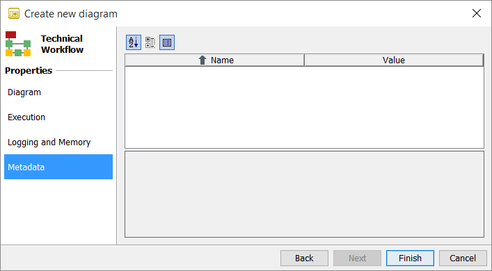
This tab lists all the metadata types available in the current diagram that can have values assigned to them.
The following functions are available via the buttons:
-
 Alphabetical sorting
 -
 Display data types
 -
 Display info-box
For information about creating metadata types refer to Using Metadata.
Indexing timestamp columns on Infinispan tables
Usage
Controls the indexing behavior for timestamp columns in Infinispan tables.
Property
indexEnabled={true|false}
Values
-
true: Enables indexing of infinispan tables -
false: Disables indexing of infinispan tables
By default, this property is set to false.
Remove timestamp column index
If the parameter is set to false after indexing is applied, it will not remove the already created index from the database.
You will have to manually remove the index from the database.
Once the index is removed, the parameter value false will prevent the Process Engine from re-indexing the tables on the next startup.