First Steps
|
You should master the processes described in this tutorial since knowledge of them is a prerequisite for the following tutorials. |
Overview of INUBIT Software
The INUBIT software consists of different components which can be combined with each other for use in the most diverse application scenarios due to their consistency:
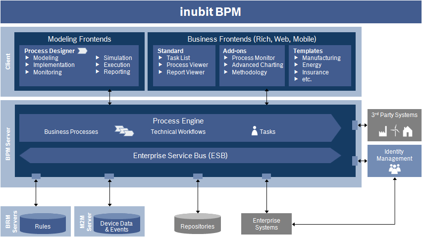
Components
INUBIT Workbench
The INUBIT Workbench is a J2SE based client with a graphical user interface for the following tasks:
-
Business modeling and simulation
-
Technical configuration of the integration segments between the different systems and business partners
-
Administration of the INUBIT Process Engine/Enterprise Service Engine and its users
-
Technical monitoring of the INUBIT software and its processes
INUBIT Process Engine /Enterprise Service Bus (ESB)
The INUBIT Process Engine/ESB are the core components of the INUBIT software. They ensure the process execution and the technical integration of systems and services.
Business Repository
The Business Repository is used for central storing and managing data and information.
Refer to Repository: Managing Files Centrally
Mobile Clients
Processes executed by the INUBIT Process Engine can also be controlled, edited and monitored via mobile terminals, for example iPhones.
Using Example Diagrams and Users
The INUBIT software contains several example users and diagrams, which you can use in the following tutorials.
Proceed as follows
Log in to the INUBIT Workbench with the user miller and the password INUBIT.
The user miller is a system administrator and therefore has extensive administrative permissions.
Staging: Creating, Testing, and Executing on Different Systems
The INUBIT software has a three-level staging process that supports creating, testing, and executing diagrams and modules on separate systems:
-
Creating locally
Diagrams and modules are created in the INUBIT Workbench in a local directory and stored on the computer on which the INUBIT Workbench is installed.
-
Publishing to the INUBIT Process Engine and testing
Once you have finished creating and editing your diagram/modules, you publish them on an INUBIT Process Engine. The diagrams and modules are then in the so-called server mode. In the server mode you can additionally use the watch mode and let scheduled diagrams execute.
Refer to Publishing Modules and Diagrams.
-
Revising locally and publishing again
Each time you publish your diagram/module, a new version is created. All versions are retained and can be displayed or activated from the version history whenever you want.
The diagram/module is copied back to the local host for editing. The version on the INUBIT Process Engine is retained.
Refer to Opening a Diagram for Editing.
-
Deploying on production system
After having finished your tests successfully, you can deploy your diagrams and, by doing so, define on which INUBIT Process Engine your diagrams are to be executed.
Creating a Diagram
All INUBIT diagrams start with an empty diagram containing different properties that you can configure.
Proceed as follows
-
In the INUBIT Workbench, open the Designer > Local tab.
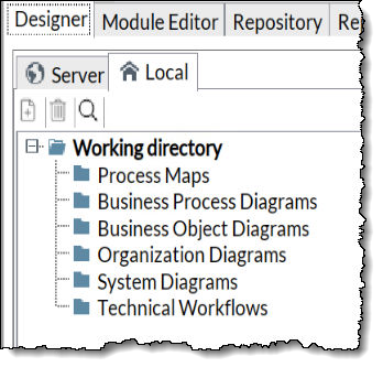
The local working directories on the Local tab contain all diagrams of the user who is currently logged in, sorted by type.
-
Select the System diagrams folder.
-
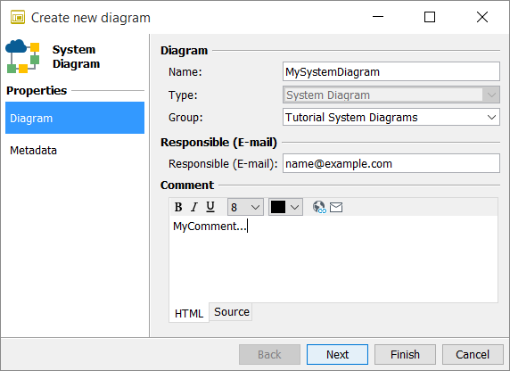
Open the context menu and select New. The following dialog opens:
-
Enter the name of the diagram and a comment (for example, the use of the diagram).
-
Click Finish.
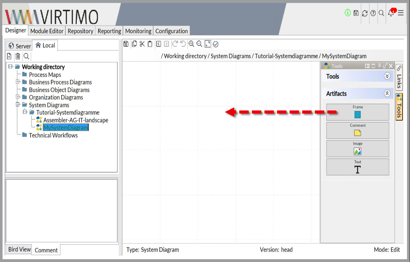
→ The dialog closes. An empty workspace is displayed:
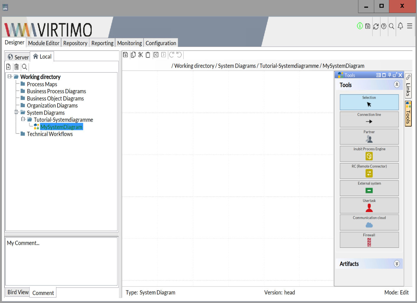
At the bottom left, the Comment tab displays the comment you entered when you created the diagram. In the workspace, you create the actual diagram using the elements displayed in the sidebar to the right of the workspace.
Inserting and Connecting Elements
The following section explains how to insert elements into a system diagram. For this purpose, we model an INUBIT Process Engine, which is protected by a firewall.
Prerequisites
You have already created an empty system diagram.
Proceed as follows
-
In the sidebar on the right, click Tools. The docking window Tools opens.
-
Click Artifacts and drag the Frame element to the workspace:
The Frame element is inserted.
-
Double-click the element. A dialog opens in which - by using the different tabs - you can enter a name for the element and define the background color and position of the name.
-
Call the element DMZ (abbreviation for Demilitarized Zone = safe zone), define the color background pink, and position the name on the top right.
-
Click Tools in the Tools docking window.
-
Drag two Firewall elements and an INUBIT element into the border element:
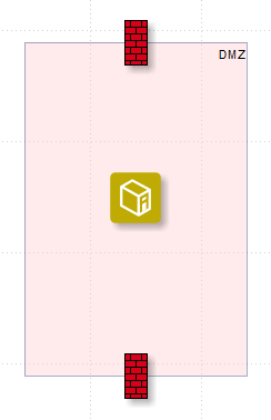
The elements are grouped automatically with the frame; if you now move the frame, the elements contained within the frame are also moved.
-
Connect the upper Firewall element with the INUBIT element:
-
Select the Firewall element using the mouse.
-
Press the Shift key and hold it down.
-
Drag the cursor out of the selected element onto the INUBIT element.
The two elements are connected with an arrow. After connecting the two elements, the arrow always points at the element that was the last to be selected.
You have different options for connecting elements or modules in a diagram: either by using the mouse and keyboard as described above or by using the context menu, refer to Connecting/Disconnecting Modules and Elements.
You can assign a name to a connection and edit a displayed connection, refer to Editing Connections between Diagram Elements.
-
-
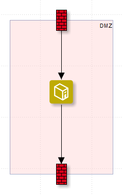
Connect the INUBIT element with the second Firewall element in the same way.
→ The result looks like this:
The diagram created in this manner is only available on your local computer at the moment. To make it accessible to other users, you have to publish it.
Publishing a Diagram
When you publish a diagram, you transfer it from your local working directory to a directory on the INUBIT Process Engine to make it available for another user group, for example.
|
Diagrams cannot be published when a module wizard window is open. |
Prerequisites
You have already created a system diagram.
Proceed as follows
-
Select the system diagram in your local working directory.
-
Open the context menu and select Publish. The following dialog appears:
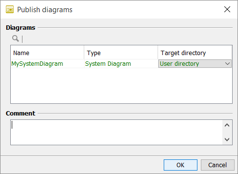
In this dialog, you define the target directory. You can publish, for example, the diagram in your own user directory on the INUBIT Process Engine or in the directory of your user group.
-
Select your user directory.
The name of the system diagram is displayed in green. This indicates that the system diagram does not yet exist in the target system.
-
Click OK. The dialog closes.
→ The diagram is published in the selected directory and displayed. This process creates a new version of the diagram.
The local version of the diagram is deleted.
When publishing a Technical Workflow including a Task Generator the option Reinitialize Existing Task becomes visible.
If selected, existing tasks in the Waiting status are reinitialized with the modified workflow data.
Opening a Diagram for Editing
You can open one or more diagrams at the same time for editing.
Diagrams can only be edited in local directories. Thus, diagrams stored on the INUBIT Process Engine are copied to a local directory.
While a diagram is being edited, other users receive a warning message if they try to edit the same diagram.
Diagrams are released for editing by other users only after they have been published or deleted in the local directory.
Proceed as follows
-
Select one or more diagrams in the Server tab.
-
Open the context menu then select Edit diagram.
→ The diagrams are copied, the copies are moved into the appropriate local directory and displayed. You can now edit the diagrams.