Report Data Collector
Usage
The Report Data Collector provides you with a convenient opportunity to generate with little effort a comprehensive documentation for your process model.
The Report Data Collector generates reports containing screenshots of the used technical and business diagrams, its modules and forms. Content and layout of the reports can be freely configured.
Requirements Under Unix/Linux for the Report Data Collector
By default, the Tomcat application servers is configured in a way to enable the use of the Report Data Collectors without a running X server.
However, without a graphical user interface, only some features of the Report Data Collector can be used, e.g. only images of workflows can be created. Form screenshots cannot be generated.
Prerequisites
To use the full functionality of the Report Data Collector, the following requirements must be fulfilled:
-
The X server is started.
-
The option
JVM_PARAMS="$JVM_PARAMS -Djava.awt.headless= true"was removed from the start script and, afterwards, the application server was restarted.You find the start script at:
<SUITE-INSTALL-DIR>/inubit/server/process_engine/bin/setenv.[bat|sh]
Creating a Process Model Report
You can let your process model generate with few clicks and define, whether the entire process model should be documented or only parts thereof and which information about the processes should be contained.
For generating the process model a pre-configured workflow is included in delivery. In this workflow the layout and the logo of the report are defined, amongst others.
Refer to Adapting the Process Model Report
Proceed as follows
-
In the INUBIT Workbench, in the File menu, select Create process model report. The report wizard opens.
The option is displayed only, when you have got a license for the Process Data Logger!
-
Let the module wizard guide you through the process of creating a report. Refer to
→ The report is generated as a PDF file and displayed immediately.
Adapting the Process Model Report
For creating the process model report a pre-configured workflow is used, in which the layout and the logo are defined, amongst others. You can adapt this workflow and, for example, extend it by a Workflow Starter in order to automatize the report generation.
Overview
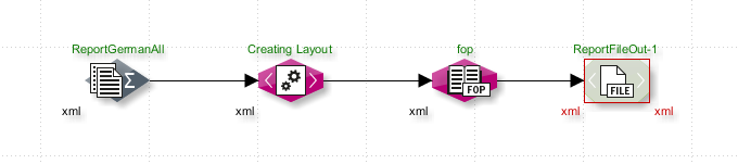
The supplied system workflow process model report collects diagram data according to your specifications, generates a PDF report and stores it to an export directory.
-
Report Data Collector
Compiles all data for the report as an XML file. Images and screenshots are saved in the* directory at
<SUITE-INSTALL-DIR>/inubit/server/ibis_root/<UserNameOrGroup>/workflow/report prozessmodell. -
XSLT Converter
Creates the report layout.
-
FO Converter
Creates a PDF file named
report.pdf. -
File Connector
Saves the PDF file to the workflow’s export directory
<SUITE-INSTALL-DIR>/inubit/server/ibis_root/<BenutzernameOderGruppe>/workflow/report prozessmodell/export.
Proceed as follows
-
Import the system workflow Process model report from the
<SUITE-INSTALL-DIR>/inubit/client/templates/workflows/Report_Prozessmodell.zipdirectory into your INUBIT Workbench. -
Adapt your workflow:
-
You define the selection of diagrams in the Report Data Collector.
-
To adjust the report to the corporate design of your company, you can replace the report logo:
-
Create a GIF file of your logo. The logo must be 450 pixels in width and 161 pixels in height.
Bigger logos are proportionally adjusted to the indicated size.
-
Save the file in the
<SUITE-INSTALL-DIR>/inubit/server/ibis_root/conf/images/directory under nameis_logo.gif.
-
-
-
Execute the workflow.
Dialog Descriptions in the Report Data Collector
Diagram Selection Dialog
Display only diagrams with the following tag
Select the tag from the list for which the diagrams are to be displayed.
Available diagrams
Expand the tree structure to view all diagrams you would like to include in the generated report.
Select one or more diagrams or diagram groups, and click the ![]() icon.
icon.
Selected diagrams
The selected diagrams are listed in the right-hand pane.
Use the  icon to remove diagrams from the selection.
Configuring the Selection Dialog
This dialog offers the following options:
-
Language of the report
Language of the pre-configured report elements, e.g. Table of Contents or generated on.
-
Language of the diagrams
Language of the diagram and element comments and of all other element identifiers. If you select Default, the language is selected which you indicated in the Default tab.
Refer to Adding Multi-Lingual Texts
-
Document title
You can assign your own title to the process model report, which is presented on the report’s front page.
Business Process Diagrams, System Diagrams, Organization Diagrams
In this section, you determine how diagrams are added to reports.
-
Picture of the Diagram
If you select this option, a screenshot of each selected diagram is added to the report.
-
Include linked diagrams
If this option is selected, all diagrams linked with a selected diagram will be included in the report. If other linked diagrams in turn have their own links to other diagrams, these diagrams will also be included in the report. This option can be used to include the entire process model in the report, provided all workflows are completely linked.
-
Element list (including properties)
If this option is selected, a list of all elements used in a diagram, including their properties is created.
Technical Workflows
-
Diagram image
If you select this option, a screenshot of each selected diagram is added to the report.
-
Module list (including properties)
If this option is selected, a list of all modules used in a diagram, including their properties is created.
-
Module-specific images
If this option is checked, the report also includes images of specific information for the following modules:
-
EDI Format Adapter: configured rules
-
Flat File Format Adapter: configured rules
-
XSLT Converter: XSLT converter table
-
Web Services Connector: WDSL file
-
Task Generator: forms
-
Display options
-
Drop shadows
If checked, a drop shadow is added to the module images.
-
Skip image rotation
If checked, a large diagram image will not be rotated.
-
Skip image slicing
If checked, a large diagram image will not be sliced.
Image directory
In the Path field, you can configure the directory where workflow images are to be stored.
By default, workflow images are stored on the server side in the following directory: <SUITE-INSTALL-DIR>/inubit/server/ibis_root/ibis_data/tmp/.
|
If the given directory does not exist, it is created during workflow execution. If an error occurs when creating the directory, an error message is displayed. |
Introductory text
(Optional) Input field for introductory text that will precede the process model report.