Basics Tutorial
Introduction
In this tutorial, we’ll build a simple IGUASU flow. This flow will
-
retrieve a file from the Internet,
-
convert data between different formats,
-
provide a REST Service,
-
and then call that Service.
In addition, we make use of the analysis tools available in IGUASU.
The finished flow:
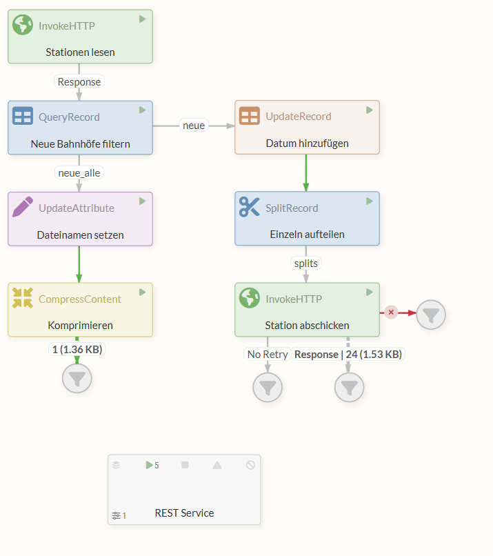
An example of the completed tutorial can be downloaded using the following link: 30min-tutorial.json.
We will now put together the flow available there step by step.
Prerequisites
A basic understanding of data formats such as CSV, XML, and JSON is helpful for this tutorial. Knowledge of HTTP methods (GET/POST), the concept of REST APIs, and simple SQL queries is also beneficial. IGUASU-specific terms and concepts will be explained throughout the tutorial.
In this tutorial, we frequently use the English terms for user interface elements (e.g., 'Properties,' 'Settings,' 'Run Schedule'), as these are how they appear in IGUASU. This makes it easier to follow the steps in the software.
Part 1: Retrieving, Filtering, and Saving Train Stations
The two most important components in IGUASU are FlowFiles and Processors.
A FlowFile is an object that flows from one Processor to the next along relations.
It consists of content (arbitrary data) and attributes (metadata).
Attributes are key-value pairs that contain information such as a file name or the URL of a request.
FlowFiles are created, modified, forwarded to other Processors, or discarded by Processors.
In this part of the tutorial, we’ll first use an InvokeHTTP Processor to retrieve a CSV file containing data on train stations in Germany from the Internet. This data is stored in the FlowFile’s Content.
In the second step, the FlowFile is forwarded to the QueryRecord Processor. This Processor filters out the entries marked as “new” from the content (i.e., the train station data in CSV format) and simultaneously converts the entries from CSV to XML. In doing so, the Processor makes use of a CSVReader and an XMLRecordSetWriter Controller Service.
With the next Processor, the UpdateAttribute Processor, we set a FlowFile attribute to determine the file name during an export.
Finally, we use the CompressContent Processor to compress the FlowFile content—that is, the XML. We’ll take a look at the compressed file at the end—but in a real-world scenario, a Processor could be used here to forward the file to an external system.
First, we’ll create a new Process Group, in which we’ll then implement our flow using Processors.
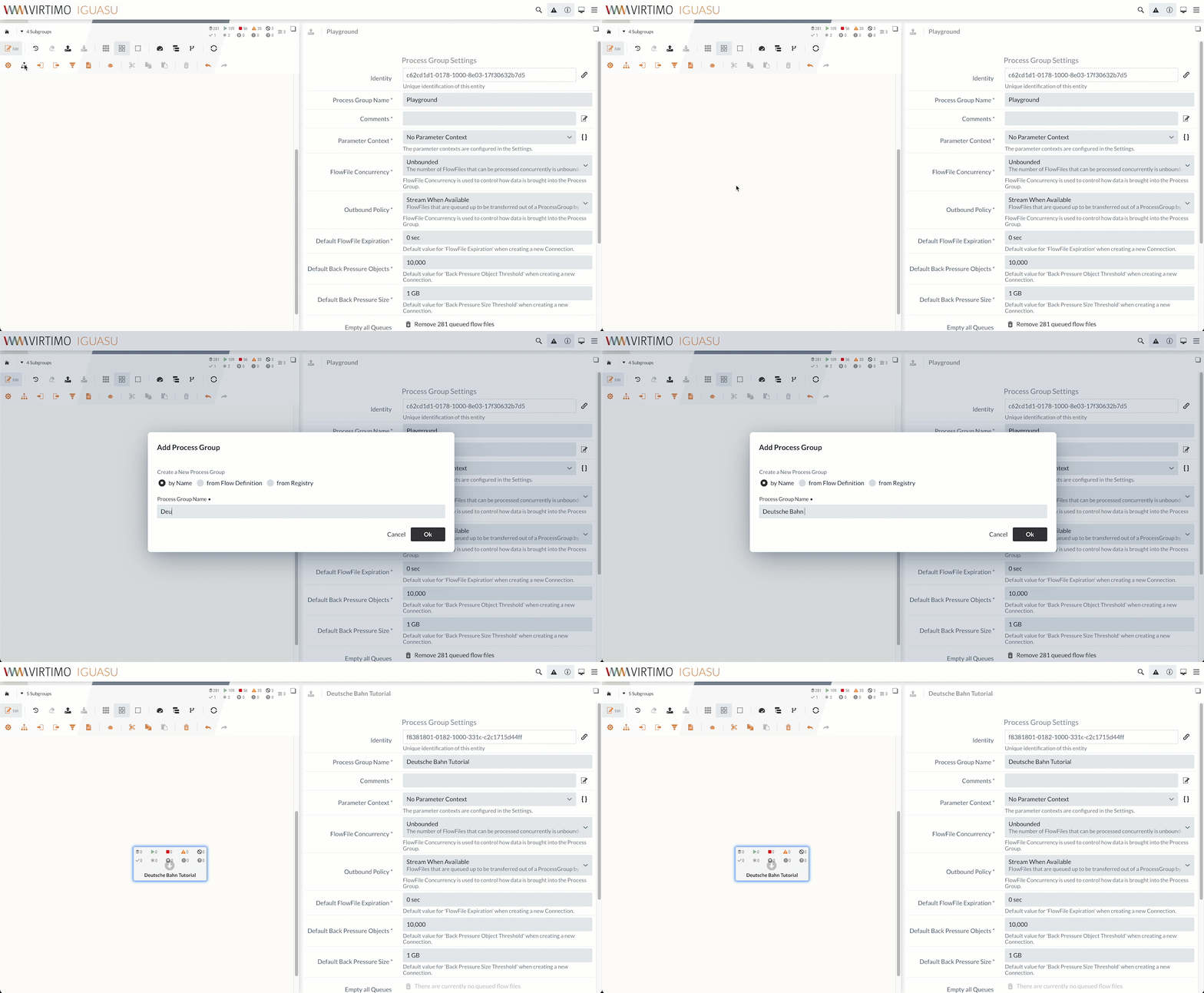
Double-clicking the created element takes us to the Process Group.
1.1 InvokeHTTP Processor (Load Stations)
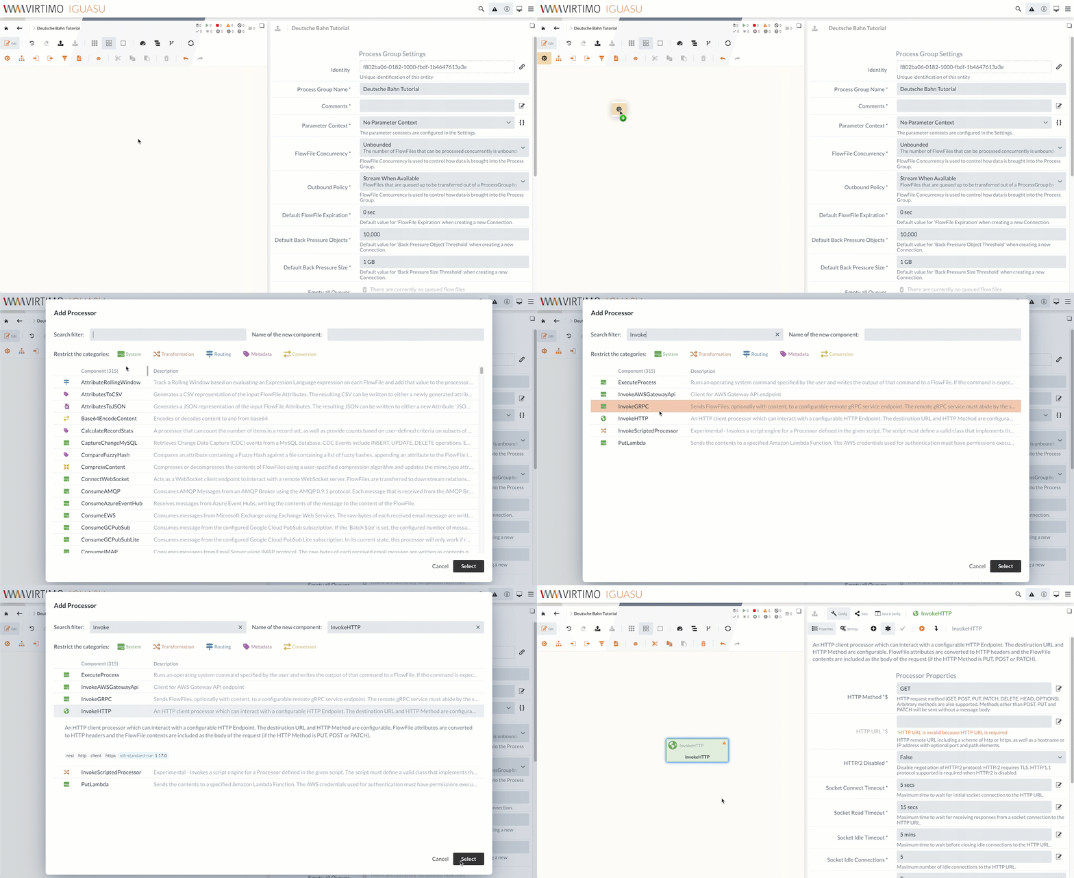
First, we’ll create an InvokeHTTP Processor.
The InvokeHTTP Processor can execute any HTTP requests.
We’ll download the CSV file using a GET request to the corresponding URL.
The file is internally converted into a FlowFile and can be forwarded to other Processors.
Processor Configuration
Processors are configured in the Properties and Settings tabs of the module editor.

IGUASU validates the processor configuration and displays in the Module Editor which properties/settings still need to be completed.
Processors that have not yet been fully configured are marked in the Diagram with a yellow warning triangle ( ).
).
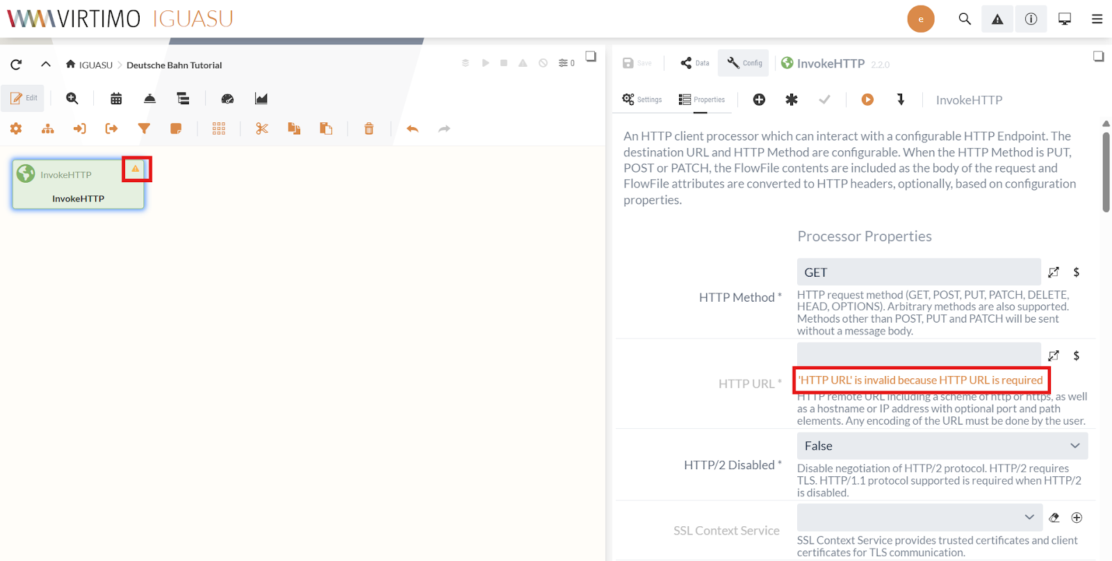
Errors related to a field are displayed directly below the field, as shown in the screenshot above for the “HTTP URL” field.
In the Processor Properties, we set the HTTP URL to the URL of the CSV file:
https://docs.virtimo.net/de/iguasu-docs/user-guide/_attachments/tutorial-files/D_Bahnhof_2020_alle.csv
The Request Type is already set to “ GET ” by default, so we don’t need to change anything else in the Properties.
In the Processor Settings, we set the Run Schedule to “60 sec” so that we check for updates every minute.
For this task, “1 day” would also suffice—the scheduler always restarts when the Processor is set to the RUNNING state via the “Start” command.
If the request is successful (2xx status code), the Relation Response is triggered, and the downloaded file is forwarded as a FlowFile along the path. By default, all relations are automatically terminated.
If a relation is used to create a link to another element in the Diagram, this automatic termination is disabled.
In this tutorial, we can let all unused relations be terminated as is.
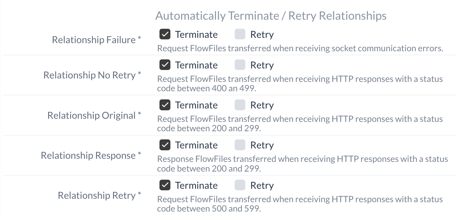
Our InvokeHTTP Processor is now ready. It retrieves the CSV file and forwards it via the Response relation. The creation of the Processor that we connect to this Response relation is described at 1.2 QueryRecord Processor (Filtering Stations).
Isolated Processor Execution
IGUASU offers the ability to run Processors in isolation from the rest of the flow, allowing you to test the configured properties.
The set configuration is used without being saved.
It can be modified as desired between executions.
We’ll now use the InvokeHTTP Processor to check whether the list of train stations is accessible at the specified URL and to see what the returned data looks like.
The execution in isolated mode can be started using the “  ” button in the module editor.
After execution, the Processor’s output is displayed in the lower half of the configuration area. You can now view the FlowFiles that are sent via the respective relation.
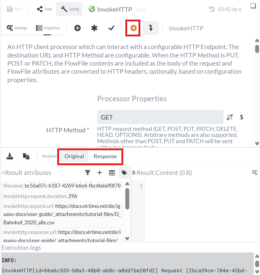
The Processor was able to successfully download the CSV file.
We select the Response relation:
-
In "Result content," we see the downloaded CSV file.
-
"Result attributes" lists the attributes of the HTTP response as well as other standard attributes.
We can see that the first row contains the headers and the data is separated by semicolons. The data shows that the “Status” column provides information about the new stations. The new stations are marked with “new.”
Later in this tutorial, we’ll look at an example of how to use the test run (see Isolated Process Execution (Continued)).
1.2 QueryRecord Processor (Filtering Stations)
In this section, we will create a Processor that reads the CSV file and filters for new stations.
We know from the test run what format the data is in and must specify the subsequent Processor for processing.
One of the Processors we can use for our purpose is the QueryRecord Processor.
|
It is useful to know what types of Processors are available and how they work. You can view the list of available Processors and search for keywords. |
The QueryRecord Processor uses SQL queries to select content from incoming FlowFiles. To do this, the data must be in a format that NiFi can interpret as records—the CSV format is one such example.
You can then use SQL to filter, transform, or aggregate the data.
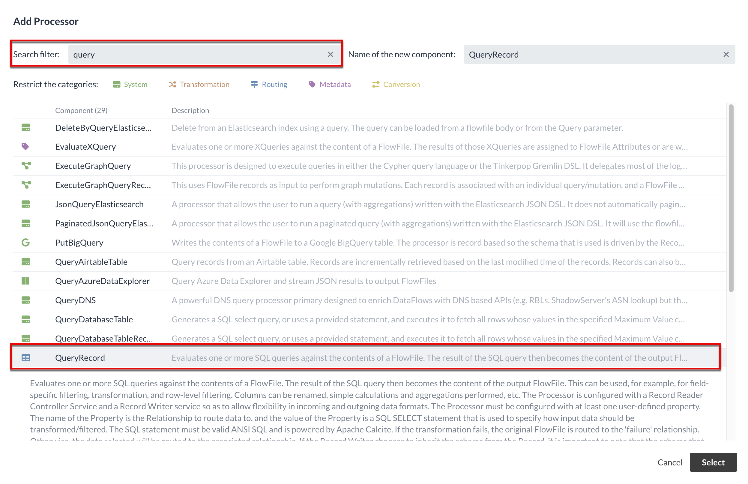
The query results are passed along as FlowFiles via a custom-defined relation.
First, we’ll add the Processor to the Diagram and connect it to the Response Relation of the InvokeHTTP Processor.
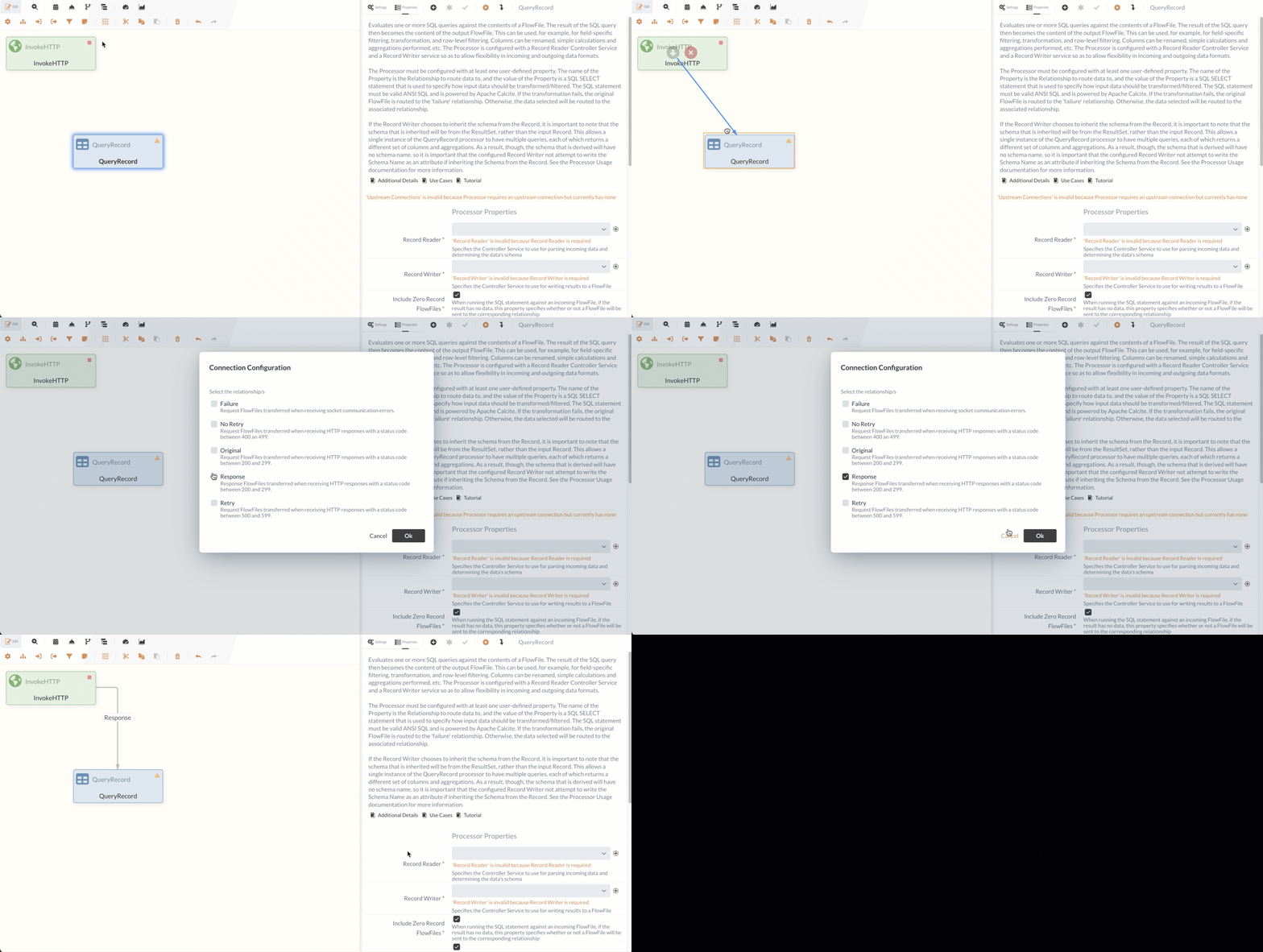
Next, we need to configure the QueryRecord Processor so that it handles the incoming data as desired.
Controller Services
Before we can fully configure the QueryRecord Processor, we need to address Controller Services. Controller Services are reusable components in IGUASU that provide central Services for Processors or other Services. Examples include reading/writing specific data formats or managing database connections.
They are configured at the Process Group level and can then be used by all Processors within that Process Group or in subordinate Process Groups. The advantage lies in the centralized management and reusability of these configurations.
The QueryRecord Processor itself is independent of the input and output formats of the data. It therefore requires two auxiliary components:
-
A Record Reader Controller Service:
This Service reads the incoming data (e.g., CSV) and prepares it for the Processor. -
A Record Writer Controller Service:
This Service receives the processed data and writes it to the desired target format (e.g., XML).
The input format of the Record Reader and the output format of the Record Writer do not have to be identical. Thus, a Processor with a Record Reader and Record Writer—such as QueryRecord—is well-suited not only for its primary function but also for converting data from one format to another.
The QueryRecord Processor receives data in CSV format from the InvokeHTTP Processor, as we observed in the test run, for example.
To read this data, a CSV Reader Controller Service is suitable as the Record Reader.
In the next step, however, we want the filtered data to be available as XML, so we use an XMLRecordSetWriter Controller Service as the Record Writer.
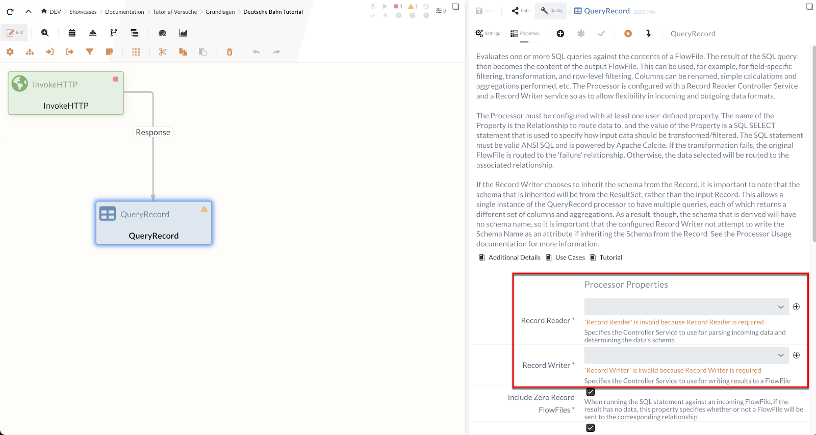
We will now create these Controller Services in the Process Group settings.
In order for the Processor to access the respective Service, the Service must be located either in the same Process Group or in a parent Process Group.
Consequently, all Processors have access to the Services located in the root Process Group.
To access the configuration menu for the Process Groups, click on the  icon.
This displays the Process Groups tree on the left-hand side.
icon.
This displays the Process Groups tree on the left-hand side.
Otherwise, the current Process Group is always displayed as the last element in the path next to the  icon.
icon.
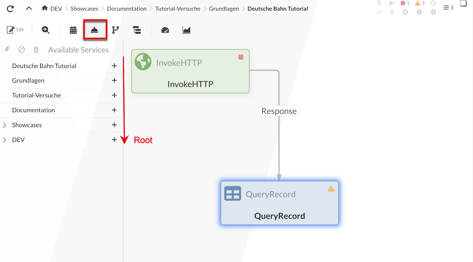
The Process Groups tree starts at the top with the current Process Group and ends with * “[Root]*”. Using the icon, we can add a Controller Service to the Process Group:
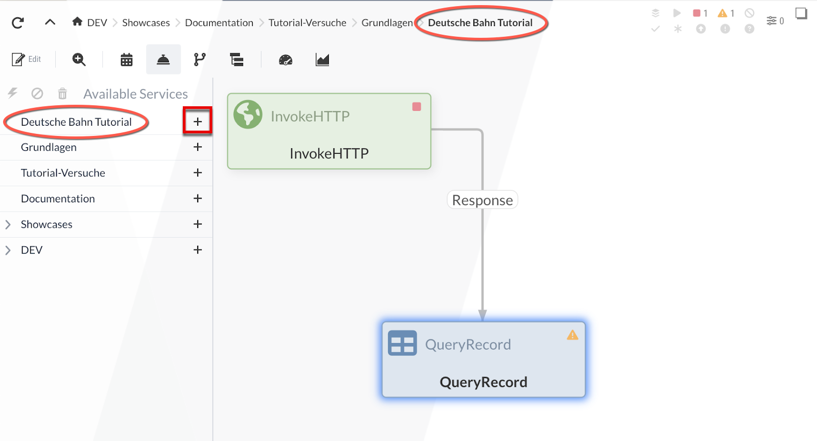
For our example, we’ll add a CSVReader and an XMLRecordSetWriter to the current Process Group. After adding them, we can start, stop, or configure the Services.
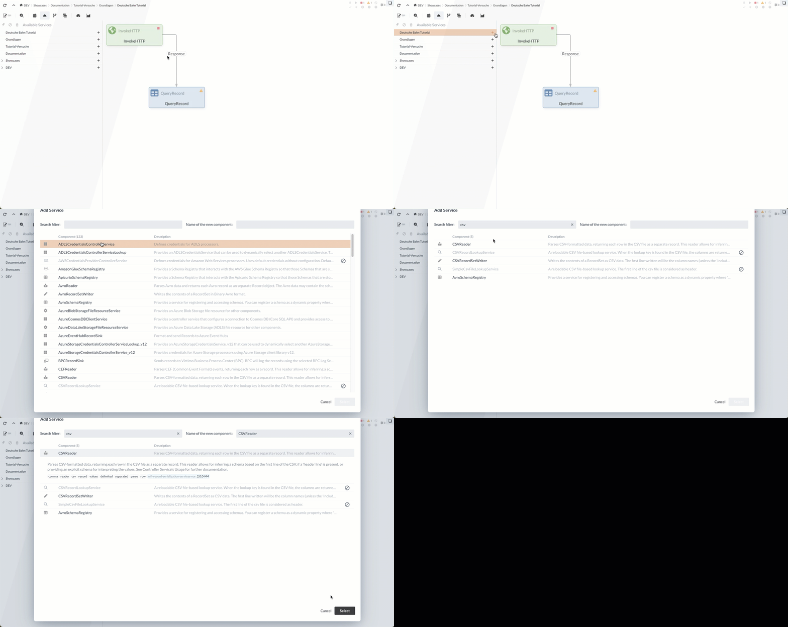
In the CSVReader configuration, we must specify the value separator as a semicolon; the remaining settings can remain at their default values.
For the XMLRecordSetWriter, we must specify a name for the root node and its entries (Root Tag & Record Tag), for example, “Root” and “Record.” These fields are optional and can be shown or hidden using the star icon in the toolbar.
The remaining settings can remain unchanged.
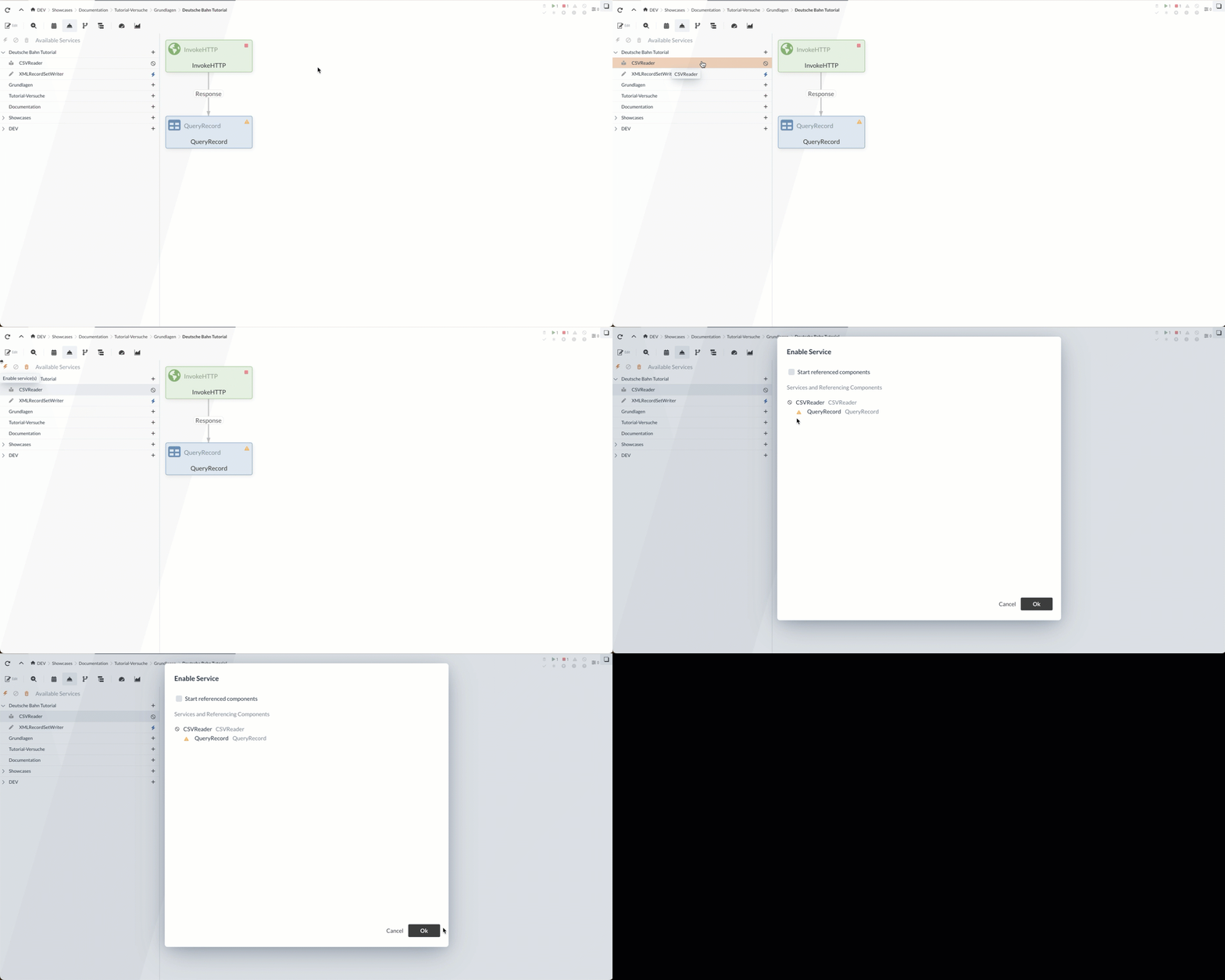
We are now finished configuring the Record Reader/Writer and can activate them so that they can be used by other Processors.
The Services are each started using the “  ” button:
|
Controller Services are not executed periodically and do not have any relationships, since they are not directly part of the flow.
They are used by Processors, Reporting Tasks, or other Controller Services. |
Now we will assign the CSVReader to the QueryRecord Processor as the record reader and the XMLRecordSetWriter as the record writer (see Processor Properties).
The input and output data types have been defined.
Therefore, the remaining task is to write the query that determines the new stations.
Before we write the query, we’d like to take a look at another feature of IGUASU that will help us create and configure Processors. The tutorial continues at SQL Query.
Data Flow Analyze - Inspection Panel (Side Note)
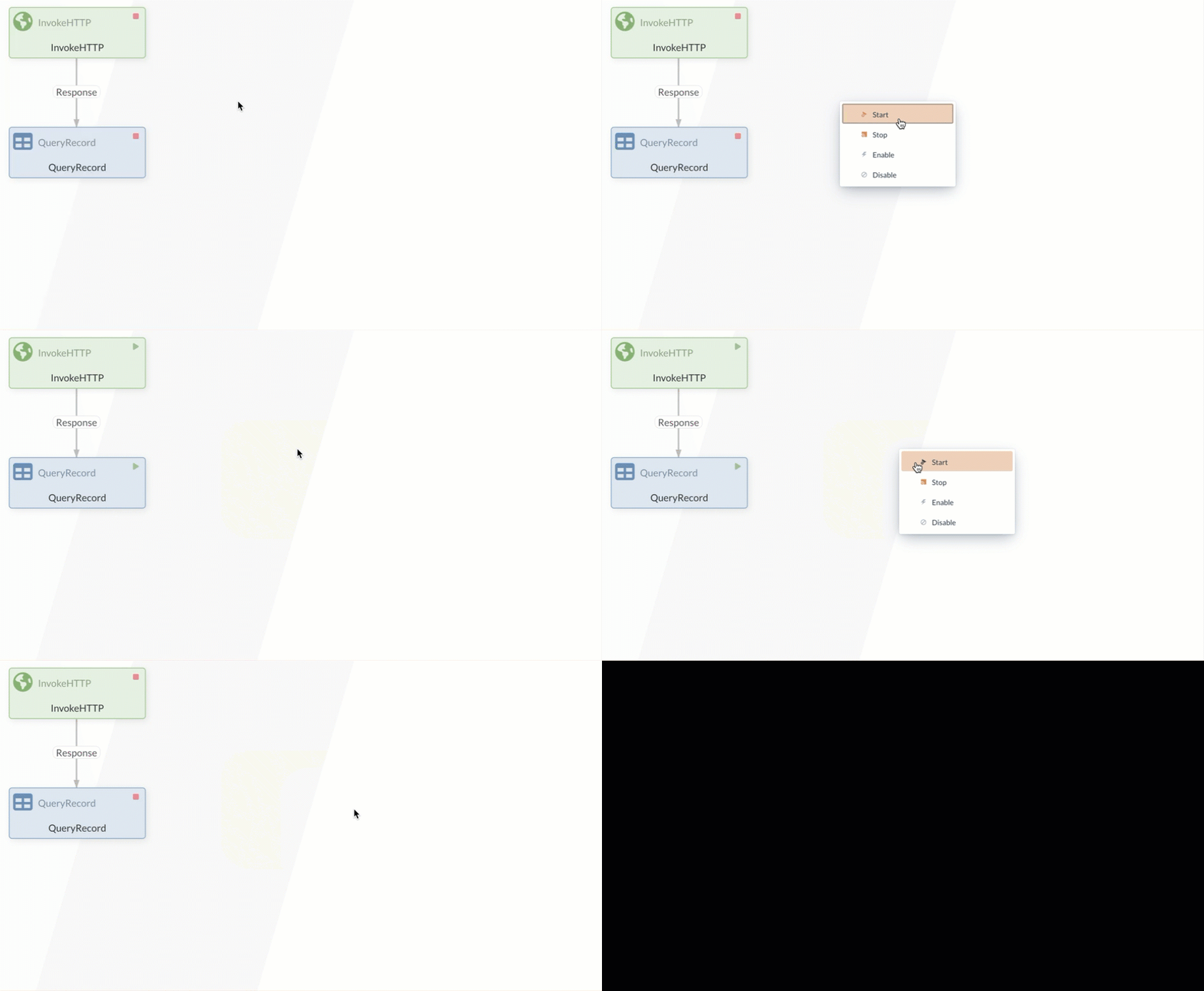
IGUASU offers the ability to view the data processed by the Processors or the data that has flowed through them. To demonstrate this in our example, we need to briefly start the flow to generate data.
To do this, right-click on an empty area to open the context menu. There, we can set all Processors in the current Process Group to the RUNNING state by selecting the Start command. Afterward, all Processors can also be stopped via the menu.
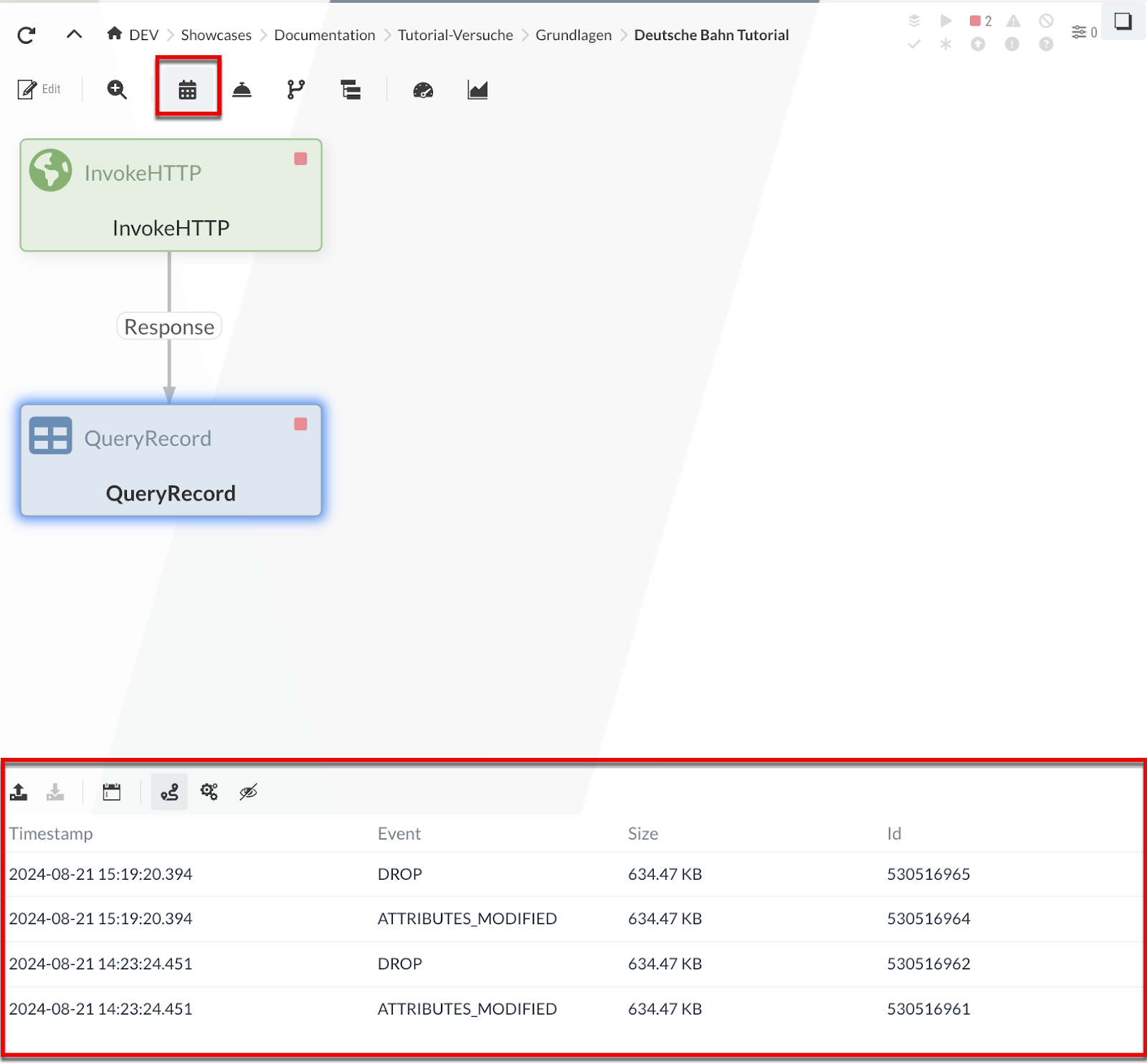
If the Event table is enabled ( button in the toolbar), selecting a Processor that has already processed data will display the history of all events generated by that Processor during execution below the Diagram. Such an event describes a processing step related to FlowFiles in the Processor.
Examples of such events:
-
Fork: The FlowFile was derived from another FlowFile
-
Route: The FlowFile is routed along a relation (with justification)
-
Drop: The FlowFile is no longer processed
After selecting an event, the sequence of the corresponding Processor executions is highlighted in the diagram.
The numbers represent the execution order—you can see which Processors were executed and in what order.
Here, these are exactly the two Processors we have so far.
In more complex scenarios, you can also see which branches were taken.
In addition, selecting an event opens the Inspection Panel.
This contains detailed information about the event as well as the input and output data from the Processor’s execution.
The input data can also be used to test a Processor (see Isolated Process Execution (Continued)).
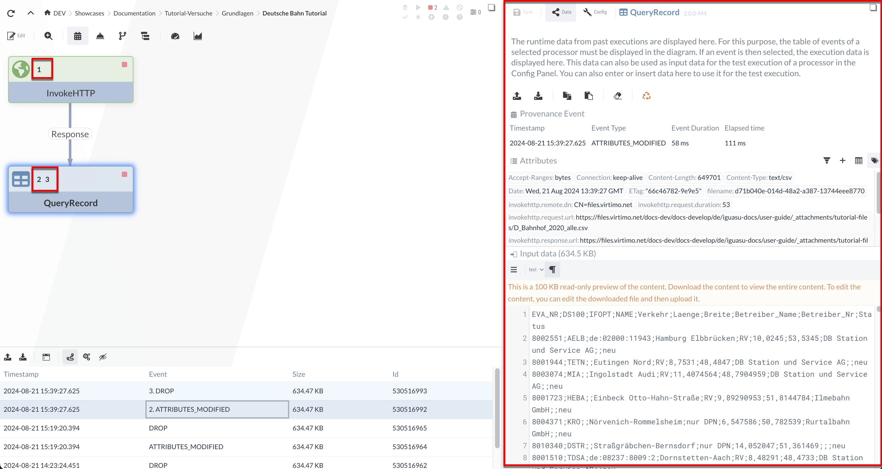
The data for the selected event remains stored in the Inspection Panel and can be used for test runs. We select the event in the QueryRecord Processor, and the CSV input is displayed in the Inspection Panel—we will use this input later (Isolated Process Execution (Continued)) for the test run.
SQL Query
Now let’s filter the CSV file for new entries using an SQL command.
Below are two sample entries from the CSV—the new stations are marked with the value * “new”* in the “Status” field.
EVA_NR,DS100,IFOPT,NAME,Verkehr,Laenge,Breite,Betreiber_Name,Betreiber_Nr,Status
8002551,AELB,de:02000:11943,Hamburg Elbbrücken,RV,10.0245,53.5345,DB Station und Service AG,,neu
8000032,NS,de:09662:28058,Schweinfurt Hbf,RV,10.212919,50.035313,DB Station und Service AG,5742,
The first entry with the EVA_NR “8002551” is therefore a new station, while the second entry with the number “8000032” is not.
We’ll use the following query to filter for the new stations:
SELECT * FROM FLOWFILE WHERE Status = 'neu'The queries are added as dynamic properties using the button.
The names of the outgoing relations correspond to the names of the properties.
We create a dynamic property named "neue_alle" with the query as its value.
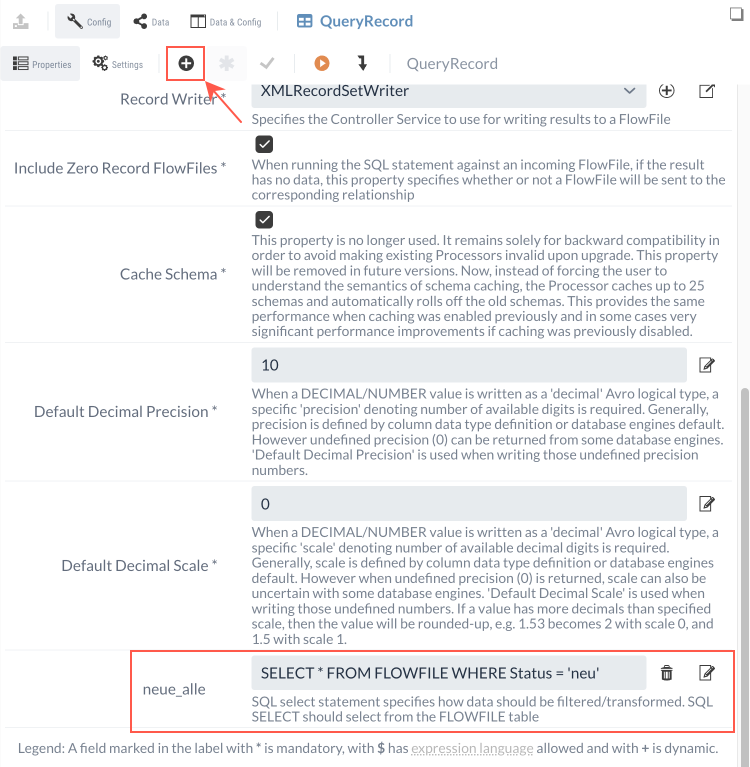
There is now a new relation named "neue_alle" that forwards the query result as a FlowFile to other Processors.
In the Processor Settings, we reconfigure the unnecessary relations to be automatically scheduled.
At this point, the QueryRecord configuration is complete, and we could move on to the next Processor.
However, it’s a good idea to check whether everything has been configured correctly and whether the Processor behaves as expected.
Isolated Process Execution (Continued)
In the following, we will verify the correctness of the QueryRecord Processor using the test run mentioned earlier (see Isolated Processor Execution). We will see if the Processor processes the data as expected by running it on a FlowFile and checking the result.
|
With the InvokeHTTP Processor, it was not necessary to provide input data (a FlowFile), since no input data is required to retrieve data from a URL. |
To use data from a previous execution, we select one of the events in the table below the Diagram.
Once the isolated execution is selected, the results are displayed in the configuration area.
|
The table appears when you select a Processor in the Diagram that has already been executed once as part of the flow. Isolated or test runs do not play a role here. |
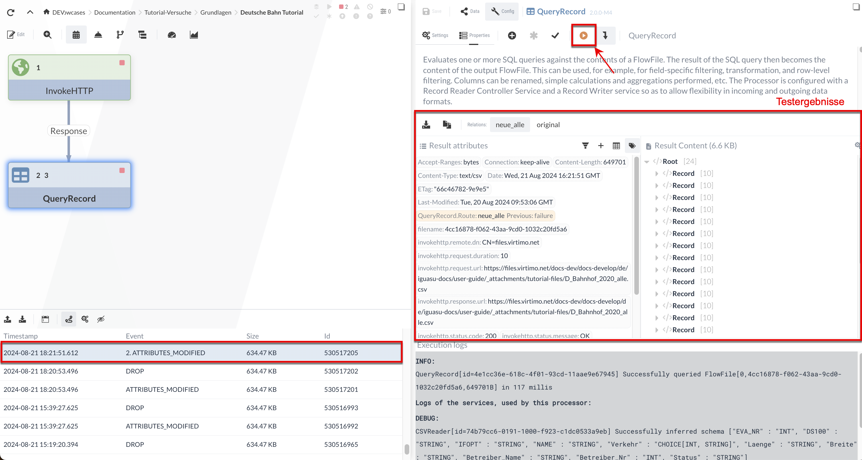
After executing via the “ ” button, we see that the QueryRecord Processor displays the results for two relations:
-
The “original” relation contains the original input data—in this case, the Processor simply forwards the input file.
-
In the “neue_alle” relation, the stations selected by the SQL query (with status='new') are output as XML.
We specified the XML record tags in the XMLRecordSetWriter. If we scroll through the result content, we can verify that only the new stations have been filtered.
We can also manually adjust or enter the input data for the test. To demonstrate this, let’s first note that in the result content, the first new station has the ID “8002551.”
We can verify that the filtering is working correctly by changing the status of this station to “old” in the input data.
To do this, we need to switch to the Data Panel and, in the Input Data section, change the status of station ID 8002551 from “new” to “old.”
Since the file is too large in our case, we need to download it and edit it in an editor of our choice.
After changing the status, we can upload the file again.
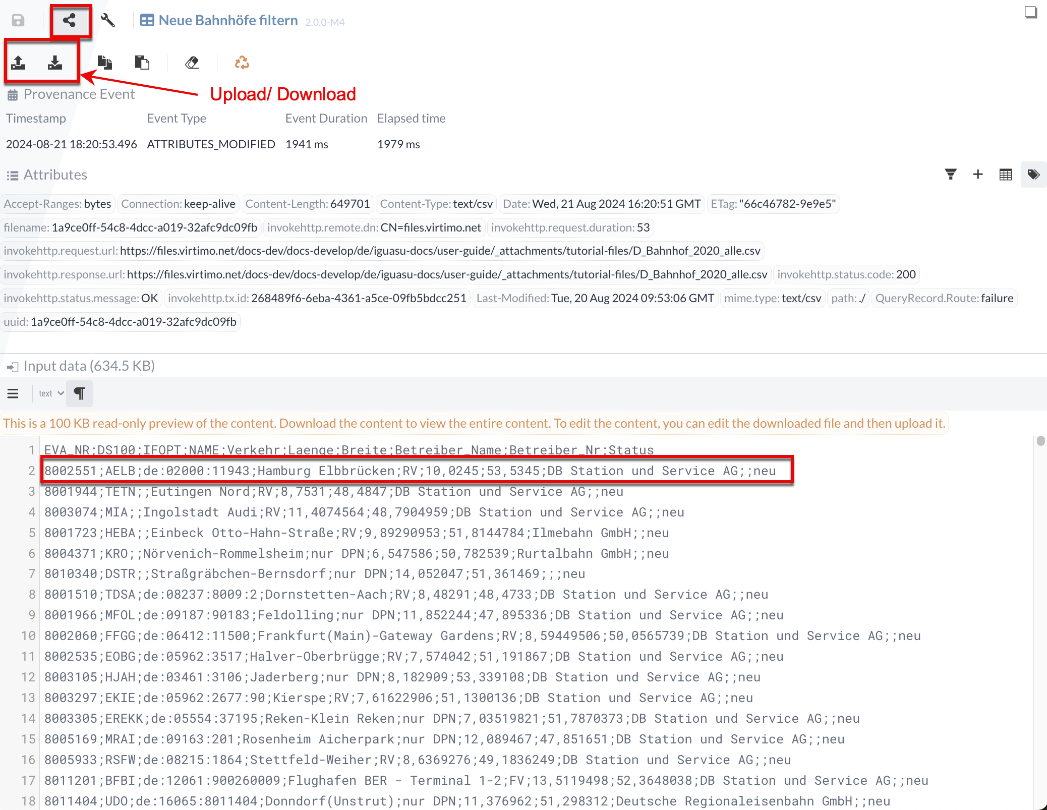
After running the query again, we see that the “neue_alle” relation no longer contains an entry with the station ID “8002551.”
Similarly, we can modify the query as desired and, for example, filter for all stations in Trier:
SELECT * FROM FLOWFILE where NAME LIKE '%Trier%'.This means you can experiment with the Processors in IGUASU and test their outputs before executing them in what may be a complex flow.
1.3 UpdateAttribute Processor (Setting File Names)
Our goal for Part 1 is to save a compressed XML file containing information about all new train stations. We could then transfer this compressed XML file to external systems using various Processors. For example, we could use the PutEmail Processor to send the file as an attachment or use PutSFTP to store it on a file server. In many cases, we pass the content as a file.
We can specify the name of this file by setting the “filename” attribute, which is then read by the Processors.
Even though we’re only downloading the content via the IGUASU user interface in this tutorial, the name of the download file is also set by this attribute.
With the UpdateAttribute Processor, we can create and modify any attributes of the FlowFiles.
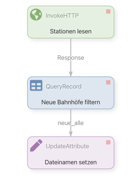
We add an UpdateAttribute Processor to the Diagram and connect it to the * “neue_alle” relation* from the QueryRecord Processor.
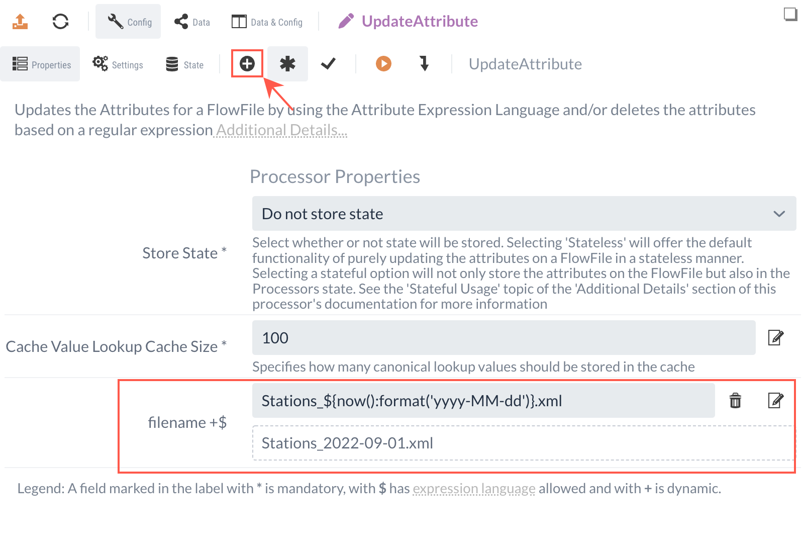
New attributes are created using the UpdateAttribute Processor by defining a dynamic property.
The name of this dynamic property corresponds to the name of the attribute to be created (or modified).
The content corresponds to the (new) value.
We want to set the content to the current date. Since the date will change daily, we cannot enter the string statically; instead, we must generate it dynamically to match the current day.
To do this, we use Expression Language, which allows us to include dynamic functions in expressions for properties.
The expression ${now():format('yyyy-MM-dd')} would return a current date such as "2020-11-19".
Since we want to save the file as XML, we can append the static ".xml" to the expression and add the prefix "Stations_": Stations_${now():format('yyyy-MM-dd')}.xml.
This results in "Stations_2020-11-19.xml".
The UpdateAttribute Processor only modifies the defined attributes of the FlowFile, not the content. We will forward the resulting FlowFile—now with the updated “filename”—to the next Processor.
1.4 CompressContent Processor (Compression)
In this step, we compress the FlowFile. To do this, we use the CompressContent Processor. We need to add the Processor to the Diagram and simply create the relationship from the UpdateAttribute.
In the settings, we should:
-
check the box next to "Update Filename" so that the file extension of the "filename" attribute is adjusted accordingly
-
set the compression rate to 9
-
set the format to "gzip."
We forward the compressed FlowFile to the last Processor.
1.5 Testing the Process
We can imagine that the compressed XML file will be forwarded to an external system in the next step or saved for backup purposes.
We simulate this step by using IGUASU’s analysis tools to download the content, unpack the file, and finally view the XML.
To do this, we route the FlowFiles through a Funnel element so we can view them later.
A Funnel is a simple element in IGUASU. It is used to collect FlowFiles from one or more incoming connections but terminates the data flow at this point. This is useful for terminating branches of a flow or for specifically “capturing” FlowFiles via the user interface for manual inspection without having them processed by another Processor.
By right-clicking in the Diagram and selecting Start, we can start all Processors in the Process Group. If we’ve done everything correctly, we should see after a short time that a FlowFile has passed through our Processors and is now waiting in front of the Funnel.
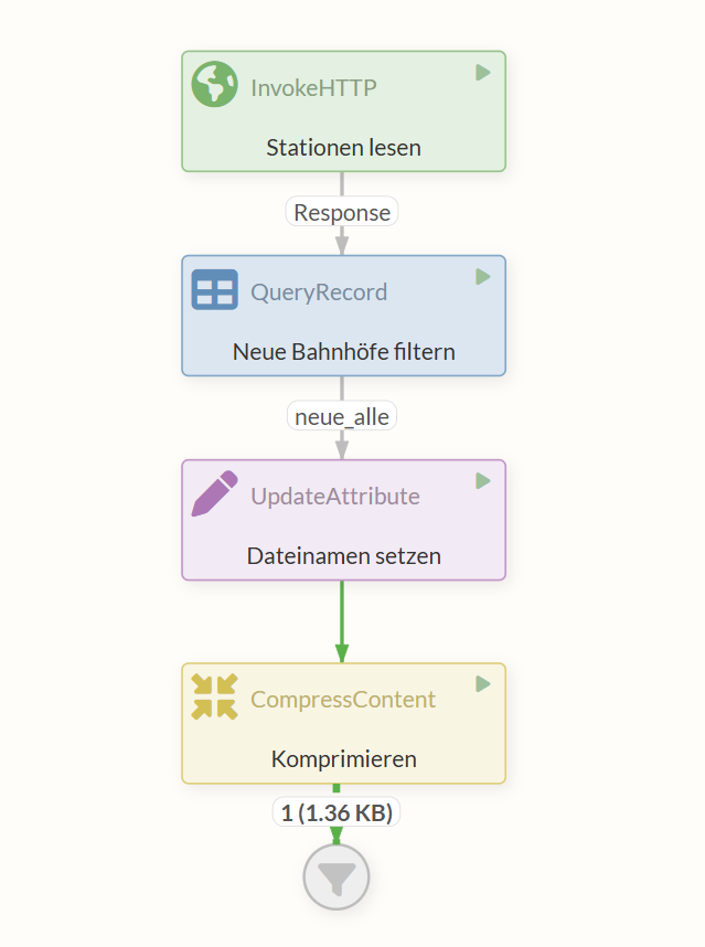
Click on this waiting FlowFile to view the FlowFile and an overview of the queue on this relation on the right-hand side.
Using the icon in the content area, you can download the FlowFile content.
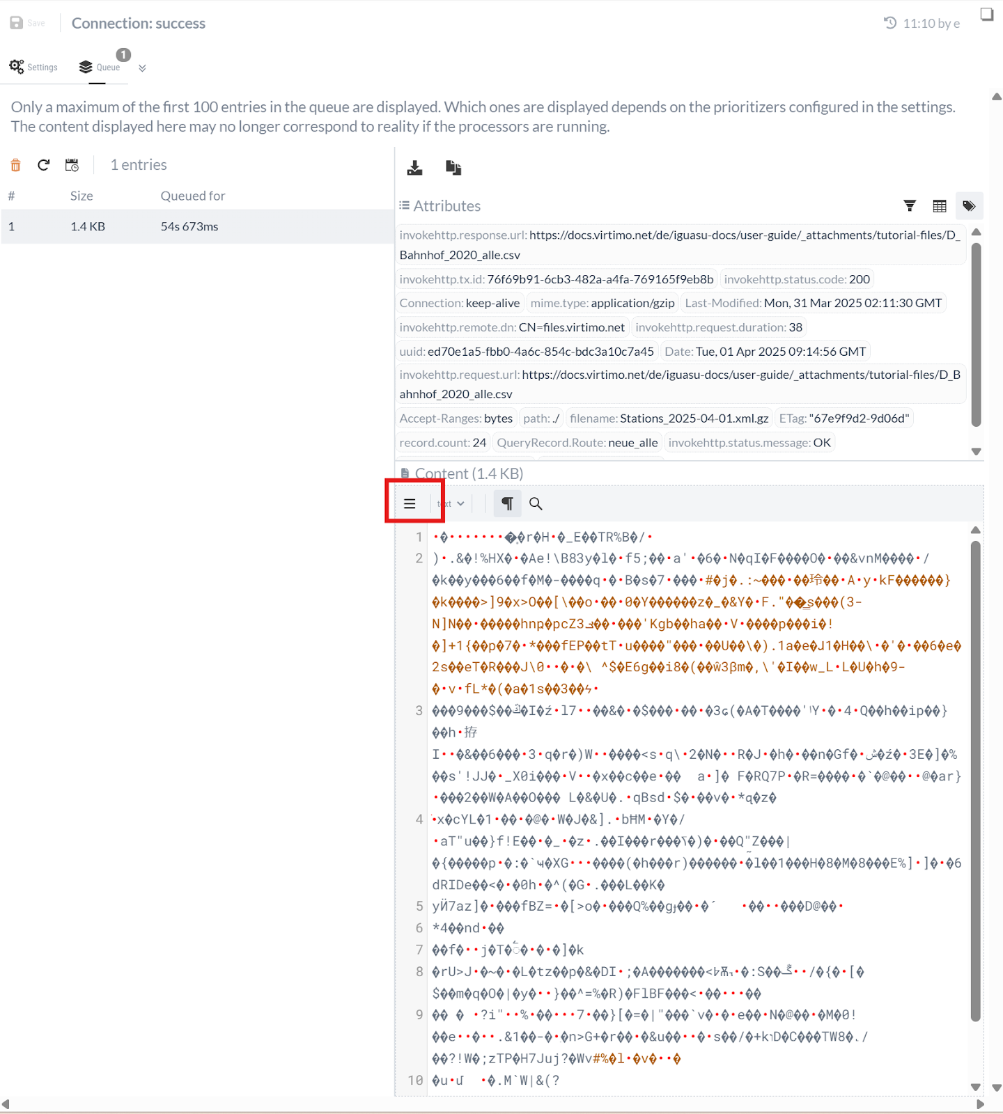
When we download the file, we should see that the name is “Stations_[yyyy-MM-dd].xml.gz”—as we specified earlier. The file extension “.gz” indicates a file compressed with gzip. If we unzip the file and open the resulting XML in an editor, we can now view the new train stations as XML.
Part 2: Implementing the REST Service
To manage the REST Service separately, we’ll create a new Process Group for it as a subgroup of the current one. We do this by dragging the button from the top bar onto the diagram area while in edit mode. We can access the new Process Group, which we’ll call “Validation via REST,” by double-clicking the corresponding element.
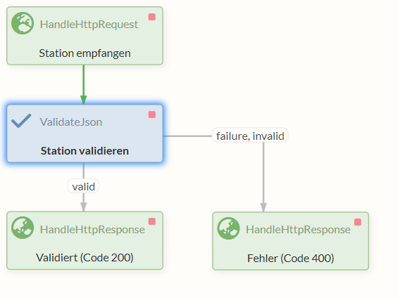
Our goal in this section is to create a REST endpoint that accepts information about train stations as JSON, validates the format, and returns a response accordingly.
To implement this, we first need a HandleHttpRequest Processor that listens on a specific Port and accepts requests.
The received requests are forwarded to a ValidateJson Processor, which checks whether the incoming message conforms to a defined format.
Finally, we send a response back using one of two HandleHttpResponse Processors, depending on whether errors occurred in any of the previous Processors.
2.1 Processing HTTP Requests
First, we need a Processor that receives and forwards the HTTP requests.
The HandleHttpRequest Processor is suitable for this purpose.
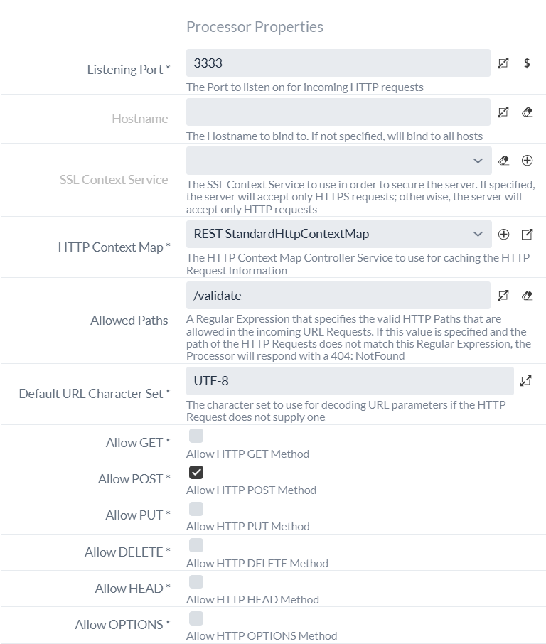
In the configuration, we set the listening port to "3333".
This is the port on which the Processor will listen for requests.
We also need to create a new StandardHttpContextMap Controller Service, which ensures that the HTTP session is maintained between the Processors.
As we saw in Part 1, we create a new StandardHttpContextMap Controller Service, but this time within the current Process Group for validation via REST.
We could also create the Controller Service in the parent Process Group “Deutsche Bahn Tutorial” or even in the root Process Group, since the Controller Services of a Process Group are also available to all sub-Process Groups.
However, we’re avoiding that here because we want to use the Controller Service exclusively within this Process Group.
When creating this Controller Service, it’s a good idea to prefix the name with “REST” to avoid confusion with other StandardHttpContextMap Controller Services.
We set the optional Allowed Paths property to “/validate”.
As a result, the Processor will only accept requests with this path in the URL.
All requests that do not go to localhost:3333/validate are automatically responded to with a 404 (Not Found) status code.
Since we are providing a REST service to which data is to be sent for validation, the client should use the “POST” HTTP method when sending the data. Therefore, we uncheck the “Allow GET,” “Allow PUT,” and “Allow DELETE” settings so that only “Allow POST” remains enabled.
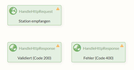
To respond to the requests, we also need two additional HandleHttpResponse Processors.
The first one should return a 200 status code to the client as a success message upon successful validation.
The other, in turn, should notify the client of an error with a 400 status code.
In a real-world scenario, it would be appropriate to handle the different error cases (invalid JSON provided, JSON schema validation failed) differently and to provide additional information about the error. For this tutorial, we will limit ourselves to returning a 400 status code for both error cases.
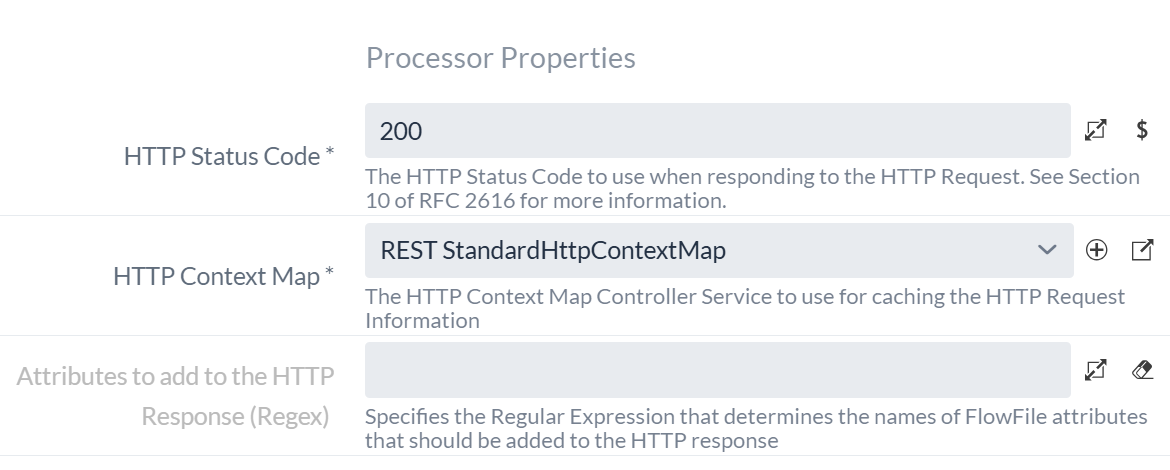
We create two HandleHttpResponse Processors and, in both cases, set our "REST StandardHttpContextMap" Controller Service in the HTTP Context Map field.
We set the HTTP Status Code field to 200 and 400, respectively.
2.2 Validating Requests
In the next step, we want to check the received JSON data for the correct format. The ValidateJson Processor is well-suited for this purpose, as it can validate JSON based on a JSON schema.
A JSON schema is itself a JSON file that specifies the structure and content of another JSON—in other words, it defines a schema. The ValidateJson Processor checks whether our JSON meets the requirements of the JSON schema.
Using the following JSON schema, we define a JSON object that represents an entry for a train station. It has exactly three entries:
-
“NR”, an integer
-
“NAME”, a string
-
“CREATED”, a string that must also be formatted as a date
{
  "type": "object",
  "properties": {
    "NR": {
      "type": "integer"
    },
    "NAME": {
      "type": "string"
    },
    "CREATED": {
      "type": "string",
      "format": "date"
    }
  },
  "required": ["NR", "NAME", "CREATED"]
}
This schema must be entered into the * “JSON Schema”* property. Otherwise, the Processor’s default settings can be retained.
The resulting configuration of the ValidateJson Processor should ultimately look like this:
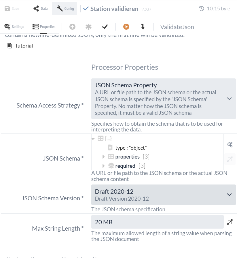
| Using the options bar of the 'JSON Schema' property, we can, for example, switch between this object view and the text view of the JSON schema. |
The valid entries are sent along the "valid" relation to the HandleHttpResponse Processor with the successful response code 200, while in the event of a validation error, the other HandleHttpResponse Processor returns response code 400.
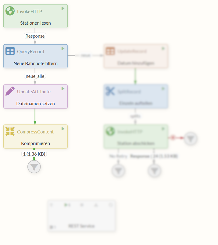
The resulting flow should look like this:
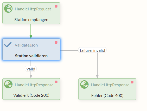
Our REST Service for verifying the data, implemented as a subordinate Process Group, is now complete and ready to be started.
Part 3: Sending Data Individually to the REST Service
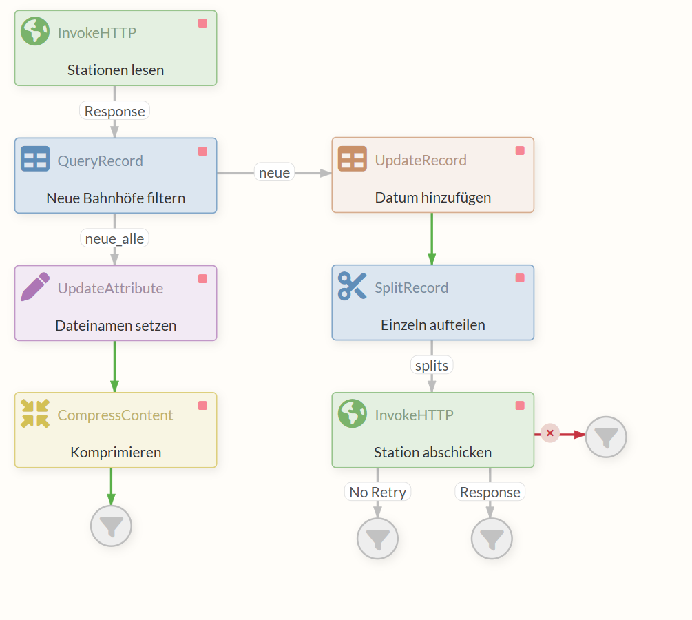
In this part, we take the existing data on new train stations and use the UpdateRecord Processor to add today’s date as a property to each entry. At the same time, we use the Processor to convert the data from XML to JSON.
The FlowFile is forwarded to a SplitRecord Processor. This Processor splits each entry for a station into its own FlowFile and forwards them so that the next Processor—an InvokeHTTP Processor—receives multiple FlowFiles, each containing a single entry (record), instead of a single FlowFile. Each FlowFile is processed independently of the others.
The task of this Processor is to pass the JSON to the REST Service created in Part 2: Implementing the REST Service, which checks the entry and returns a response based on the result of the check.
In this tutorial, we use our own REST Service to demonstrate both sides of the communication. In real-world scenarios, you would typically call an external REST Service.
3.1 Customize QueryRecord (reduce to station number and station name)
In this part, we want to retain only the station number (EVA_NR as NR) and the station name (NAME) from the CSV data for the stations to provide a clearer overview.
We can use the QueryRecord Processor we created earlier to remove all other information and, as before, convert the data to XML format at the same time.
To do this, we create a new Dynamic Property named “new” and set the appropriate SQL statement as its value.
SELECT EVA_NR as NR, NAME FROM FLOWFILE
where Status = 'neu'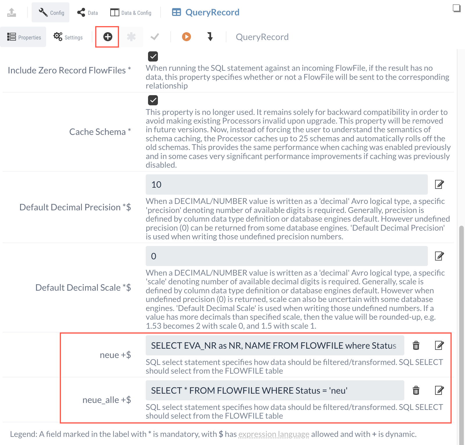
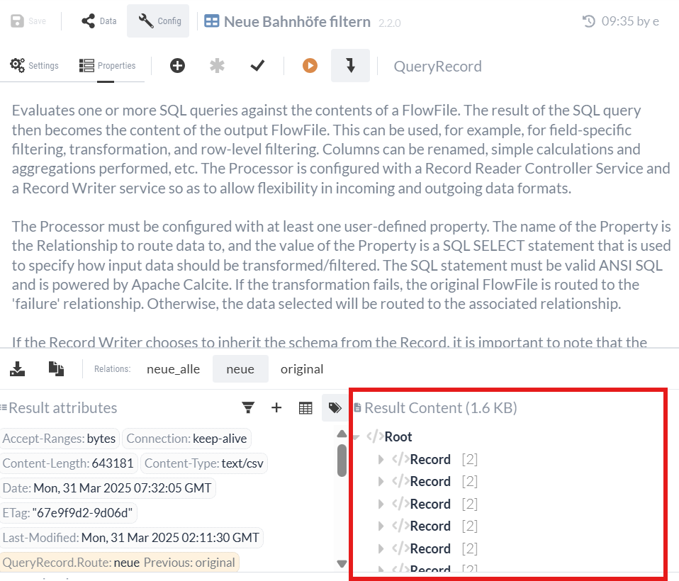
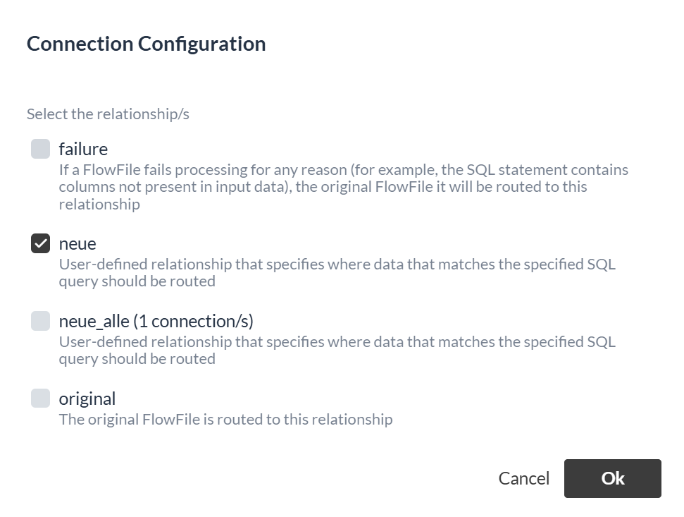
Both “neue” and “neue_alle” are now outputs of the QueryRecord Processor. To verify the functionality, we can run a test using the existing CSV data (see Isolated Process Execution (Continued)).
3.2 UpdateRecord Processor (Add Date)
We want both Part 1 and Part 2 to be executed every time the flow runs. Therefore, we will not modify Part 1, but rather let both parts exist and run in parallel.
To do this, we connect our next new Processor, the UpdateRecord Processor, to the “new” output of the QueryRecord Processor that we just created. This processor thus forwards two different FlowFiles to two separate outputs, which are processed independently of one another.
In addition to the station number and name, we now want to add the current date to each entry. This is to indicate that the information is up to date. We’ll use the UpdateRecord Processor for this.
As with the QueryRecord Processor in Part 1, we need to specify a Record Reader Controller Service and a Record Writer Controller Service. Since we receive our data in XML format from QueryRecord, we need an XMLReader.
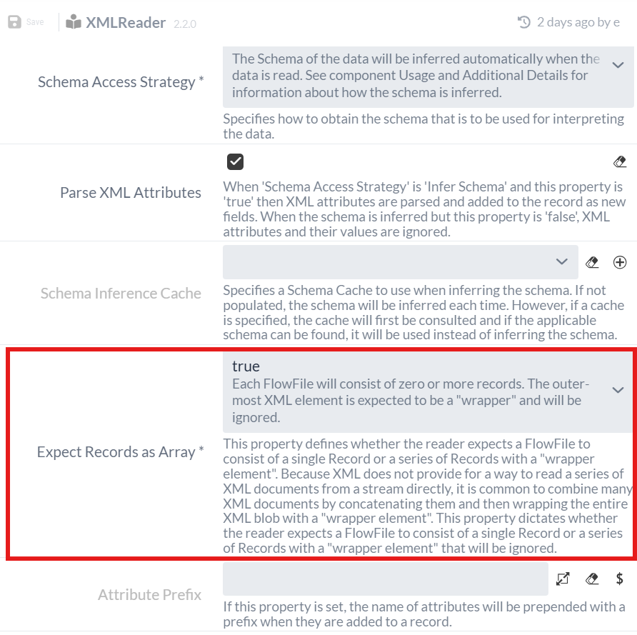
As in Part 1, we must add this as a Service to the Process Group and set the “Expect Records as Array” option to * “true”* in the configuration, since the data arrives as an array in the XML (see “Result content” at Test run of the QueryRecord Processor).
For the Record Writer, we’ll use a JsonRecordSetWriter Processor with default settings. This converts the records from XML to JSON format, since we ultimately want to send a JSON response to the REST interface.
Next, we’ll add a Dynamic Property using the button.
We’ll use the expression for the current date again and add it to each record.
The name of the Dynamic Property specifies the name of the additional field in the record.
(This procedure is similar to the previous step with the UpdateAttribute Processor in the first part of the tutorial; see 1.3 UpdateAttribute Processor (Setting File Names).)
|
Since the value is specified via a Record Path, the name of the Dynamic Property begins with a slash ('/'), e.g., |
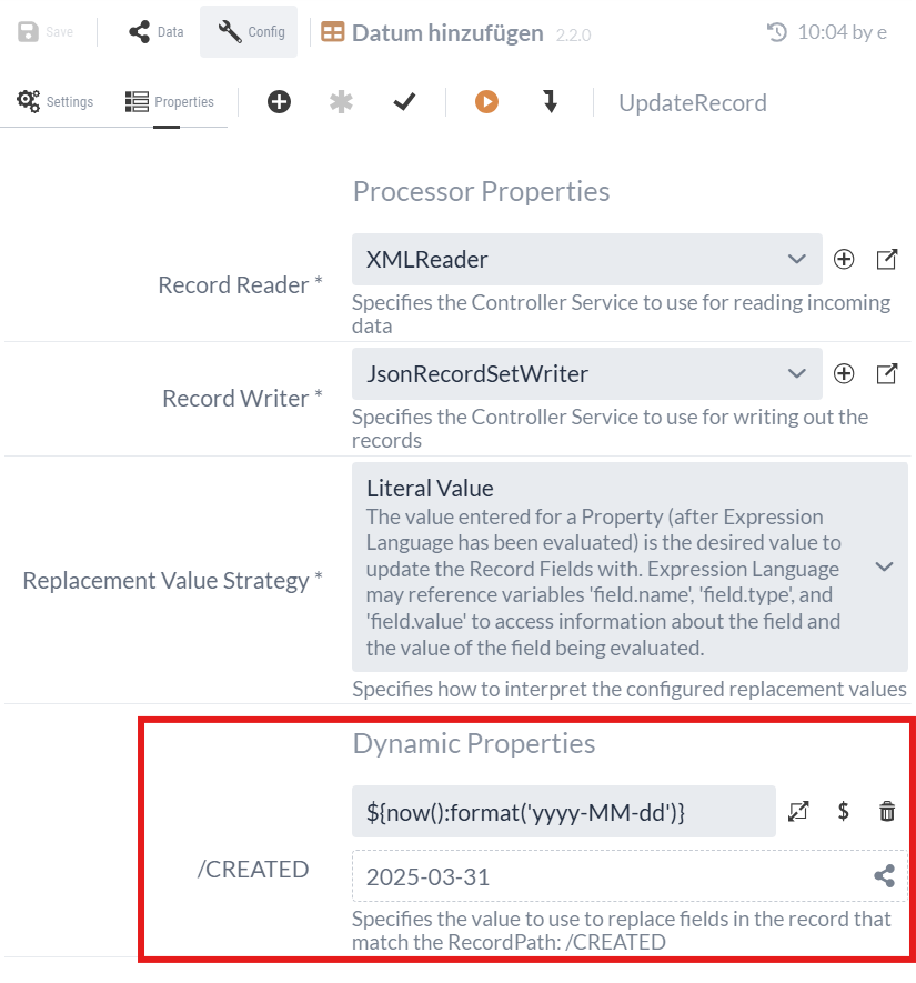
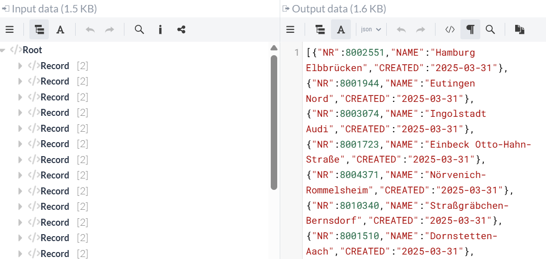
During execution, the stations are converted from XML to JSON and tagged with the current date after the "CREATED" name:
3.3 SplitRecord Processor (Split stations individually)
We now forward the FlowFile containing the JSON to a SplitRecord Processor. Using this Processor, we will split the list of stations into individual elements so that the REST service can be called for each station.
Since the data arrives in JSON format, we need a JSONTreeReader as the Record Reader, which we must again create as a Controller Service.
The default settings can be retained.
For the Record Writer, we can use the JsonRecordSetWriter that we previously created for the UpdateRecord Processor.
    Record Reader: JsonTreeReader
    Record Writer: JsonRecordSetWriter
Records Per Split: 1
3.4 InvokeHTTP Processor (Submit Train Stations)
Each FlowFile from the SplitRecord Processor is now forwarded to another InvokeHTTP Processor. With this Processor, we call the REST Service to validate the JSON data and pass the FlowFile content—that is, the JSON containing the entry for a train station—as the body.
HTTP Method: POST
HTTP URL: http://localhost:3333/validate
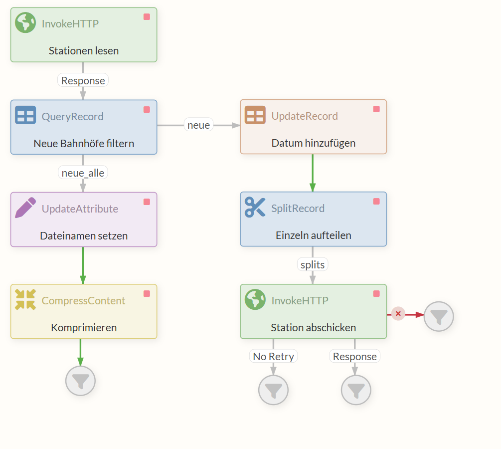
The flow now looks as follows:
3.5 Executing the completed flow
Right-click in the Diagram and select Start to launch all Processors.
The top InvokeHTTP Processor sends an HTTP request to retrieve the CSV file. As soon as it receives the file via the response, the FlowFile is passed on to the QueryRecord Processor.
Here, the flow splits into two branches.
On the left, an XML file containing all new stations and all available information is passed to the UpdateAttribute Processor via the “neue_alle” relation.
The UpdateAttribute Processor sets the “filename” attribute, which determines the name of the file that will be output later.
The FlowFile, which contains both content and attributes, is passed on to the CompressContent Processor, where the XML is converted into a gzip-compressed data stream. This data stream ultimately ends up in the relation to the Funnel, where we can view and download the content.
On the other branch of the flow, the QueryRecord Processor passes an XML file via the “new” relation that also contains data on the new train stations—though only the names and numbers. The UpdateRecord Processor then adds additional information to each of these entries: today’s date.
At the same time, it converts the data into the JSON format expected by the REST endpoint. This JSON containing station entries is then sent to the SplitRecord Processor, where each entry is individually packaged into a FlowFile, so that multiple FlowFiles—rather than just one—now leave the Processor.
Each of these FlowFiles passes individually through the “splits” response into the InvokeHTTP Processor, which sends a request containing the JSON from the content to the REST Service we implemented for each FlowFile.
Each FlowFile with valid JSON data produces a response from the REST service with status code 200 and is accordingly routed to the “Response” relation.
Outlook
This tutorial has shown you the basics of creating flows with IGUASU.
For real-world use cases, IGUASU offers far more possibilities.
These include, for example, advanced error-handling strategies and many other specialized Processors and Controller Services that go beyond the scope of this introduction.
