Hybrid Cloud Tutorial
Introduction
There is a need to integrate various systems and Services, both on-premises or in a data center and in the cloud.
Virtimo offers the INUBIT product for integrating on-premises systems. IGUASU is available for connecting various systems and Services from the cloud or the Internet.
It now makes sense to connect these two worlds. The hybrid cloud connection exists precisely for this purpose. It connects INUBIT and IGUASU in an innovative, secure, and easy-to-use way.
To achieve this, there is the IGUASU Connector in INUBIT and INUBIT Processors in IGUASU.
Client-to-Cloud-initiated duplex connection
To ensure the highest possible security while minimizing the configuration effort required for the home network in terms of firewalls and port forwarding, the connection between the on-premises system and the cloud is always established by the on-premises system—i.e., INUBIT.
The connection, in the form of a Secure WebSocket, is then maintained continuously. Should it ever be interrupted, it is immediately reestablished by the on-premises side (INUBIT).
Through this connection, workflows can be initiated on the other system from both the on-premises side (INUBIT) and the cloud (IGUASU).
Maximum security through the use of mTLS
The connection is always secured by mTLS/SSL. This means that both sides (IGUASU and INUBIT) prove their identity using certificates, and the connection is secured via SSL.
The necessary certificates are generated by IGUASU. For INUBIT, they must be downloaded and configured for the connection. In IGUASU, once they are generated, they simply need to be configured in the corresponding Services.
Example Use Cases
As described above, once the systems are connected, processes in the other system can be initiated from either side. Possible scenarios that could be implemented include:
INUBIT → IGUASU
-
A specific system in the cloud—for which IGUASU provides a simple connection—is to be called from a local workflow in INUBIT
-
Writing a message to an AWS system such as S3 or Kinesis
-
Communication with a Kafka system —for example, writing to a Kafka topic and receiving messages from another topic, which then trigger INUBIT workflows
-
-
Parts of the processes that have been implemented with INUBIT so far are to be made dynamic, so that they can handle high peak loads via scalable flows in the cloud
-
This could apply to parts that generally generate particularly high loads
-
But it could also apply to areas that place high demands on the system only at certain times—such as online stores during Christmas or the sending of notifications at specific times
-
IGUASU → INUBIT
-
A flow in the cloud will be used to retrieve a customer’s address, with the customer data itself stored on-premises
-
A specific data record can be retrieved in a targeted manner. The database itself does not need to be accessible on the Internet for this; instead, only the specific data is transferred via the two securely connected integration products
-
-
An internal Service that must under no circumstances be publicly accessible on the Internet is required in a cloud flow
-
The goal is to access the internal SAP system or an AS/400
Contents of this tutorial
To illustrate the interaction between a local INUBIT installation and IGUASU in the cloud, this tutorial shows you how to establish the connection between the two components.
In this tutorial, you will learn how to create the necessary certificates in IGUASU and how to use them to ensure secure communication between the applications. It also demonstrates how to configure the INUBIT-specific Processors in IGUASU so that messages can be received from INUBIT and data can be sent back to the on-premises installation.
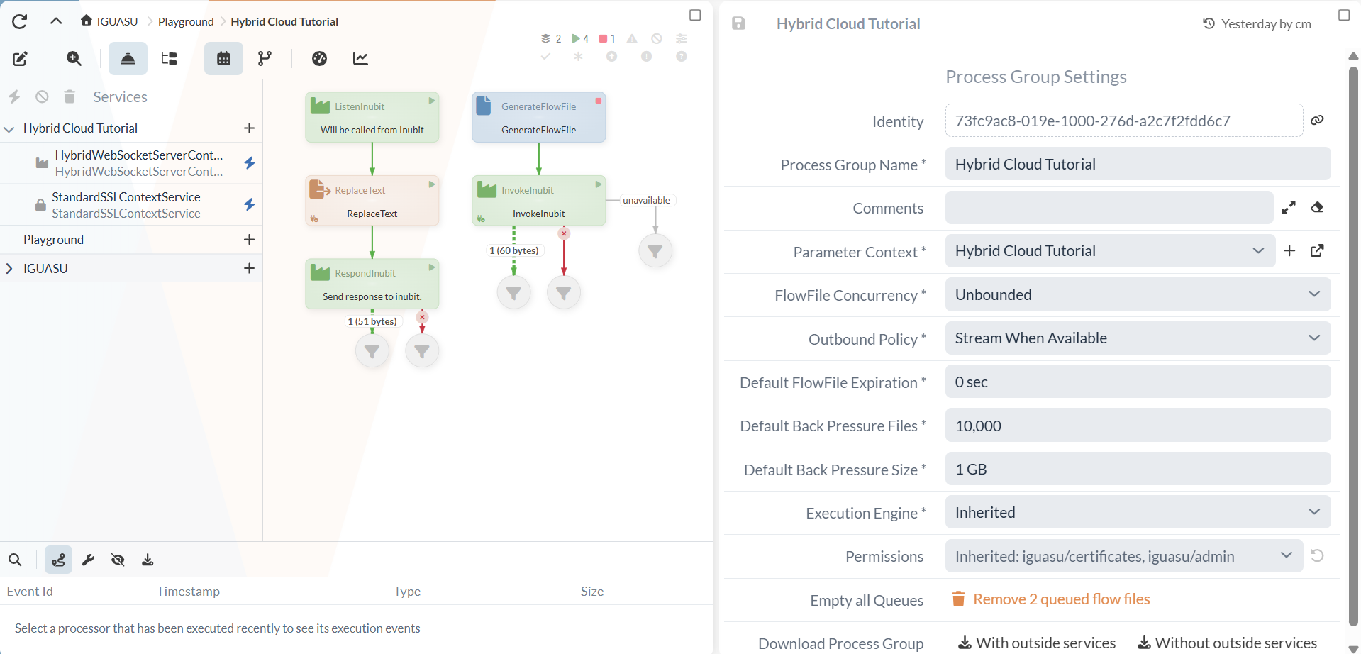
The following tutorial was created using IGUASU 4.3.0, the INUBIT Process Engine, and Workbench 8.1.14 on Windows 11. The final flow for both communication options is shown in the following figure:
Part 1: Configuring the Endpoint
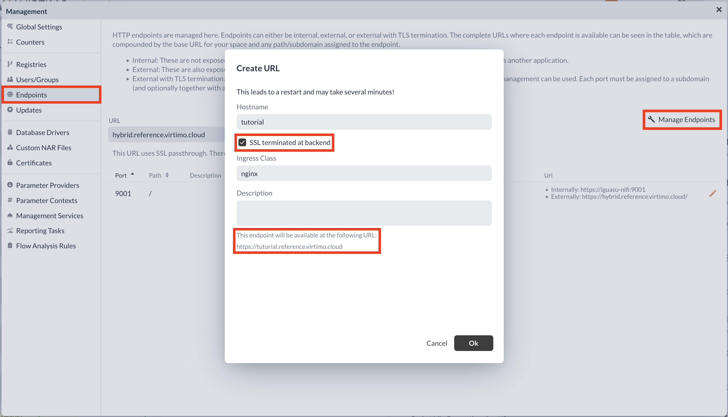
Before you begin creating the certificates, the correct endpoint must be configured in IGUASU. This endpoint is used by the IGUASU Connector in INUBIT to establish a connection to your IGUASU instance. In IGUASU, navigate to the endpoint configuration window by opening the global menu and selecting “Management” from the menu.
|
You need the appropriate permissions in IGUASU to view the endpoint configuration window. If you cannot see the configuration window in the settings, contact your administrator. |
Select the Add URL option and configure a URL with the following properties:
-
SSL terminated at backend: The endpoint will be accessible from your INUBIT system via a TLS-terminated connection.
-
Hostname: Select an appropriate SSL pass-through hostname. This will be appended to the URL that the IGUASU Connector will use in INUBIT.
Then select the URL and add a Port as the endpoint. For the purposes of this tutorial, port 9003 is used.
Part 2: Creating the Required Certificates and Keys
To enable a secure connection between the two components, the corresponding certificates and keys must first be generated. IGUASU offers the option in the Parameter Context to generate keystores that contain the required elements.
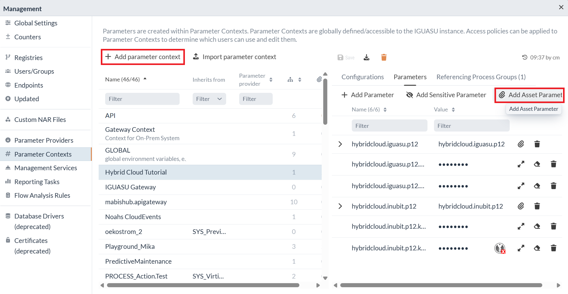
To access this feature, open the global menu and navigate sequentially to the Management and Parameter Context items. As part of this tutorial, the “Add Parameter Context” button is used to create a new Parameter Context, within which the two required keystores are then generated. To do this, the “Add Asset Parameter” button is used below, which allows you to select the “Generate Private Key/Certificate” option.
|
To view the parameter contexts, you need the appropriate permissions in IGUASU. If you are unable to view them, please contact your administrator. |
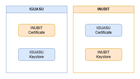
In the Certificate Manager, you can now view all existing keystores in a tabular list. For this tutorial, two new keystores (private key & certificate) are required, both of which can be generated in IGUASU. This means that two pairs of private keys and certificates will be generated. This is necessary so that both sides can prove their identity. Thus, IGUASU and INUBIT each have a private key and certificate pair to authenticate each other when communicating via mTLS. After successful configuration, the certificate belonging to IGUASU should be linked or uploaded on the INUBIT side, and the certificate belonging to INUBIT should be linked on the IGUASU side.
The following image shows how the “Generate Private Key/Certificate” option is used in this tutorial to generate a new key and certificate. The “Subject Alternative Name” input field must match the endpoint URL from Part 1 of this tutorial for the IGUASU keystore. This does not matter for the INUBIT keystore.
|
For INUBIT Workbench versions prior to 8.1.10, a private key password is not supported; therefore, the corresponding field should be left blank during creation. Starting with INUBIT Workbench version 8.1.14, it is recommended to set a private key password. Keep all passwords in a safe place, as you will be reopening the keystores later in this tutorial. |
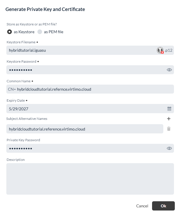
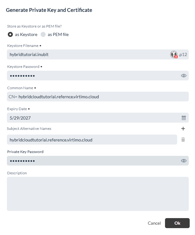
The newly created keystore will then be visible; you can download the corresponding keys via its parameter dialog. A download function is available there for exporting the entire keystore.
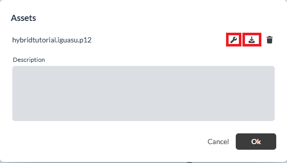
One level down is the editing function, which allows you to download the private key and certificate separately after successfully entering the correct keystore password. You can use the key button to download the private key and the public key/certificate.
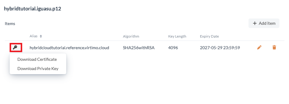
Both the certificates and the private keys are required when configuring the Services in IGUASU and the connectors in INUBIT, which is described in more detail in the following sections of the tutorial.
Part 3: Configuring WebSockets and SSL Services
Once the keystores have been created, you can configure the Services required to use the INUBIT Processors. As part of this tutorial, a new process group is created in IGUASU for this purpose. First, the StandardSSLContextService is required; this service retrieves the keystore information to enable secure communication between the components.
In the StandardSSLContextService, the path where the keystore is stored must be specified to configure it. To do this, the Parameter Context must be assigned to the created process group. Clicking the empty field within the process group takes you to the settings where you can assign the correct Parameter Context.
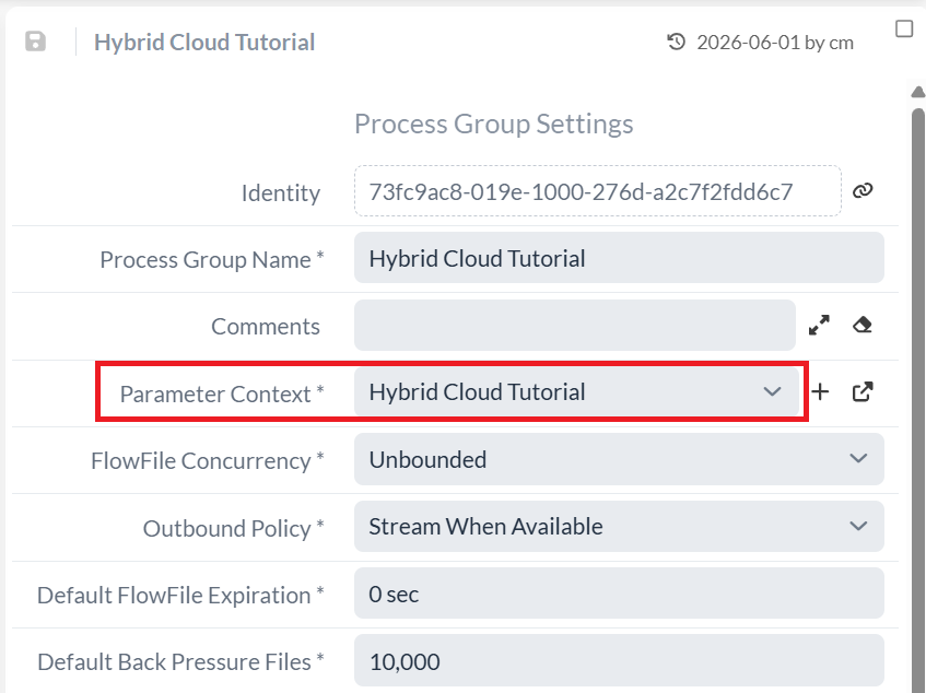
Next, the keystore filename and truststore filename must be set in the StandardSSLContextService.
You can use Expression Language for this so you don’t have to specify the entire path.
The call ` #{<Name des Keystores>} ` retrieves the stored keystore path.
Additionally, the keystore password—which was previously defined in the keystore window—is required to access the corresponding keys.
If a key password was also specified during creation, this must also be entered in the Service.
Since the keystores were created in IGUASU, the default type PKCS12 can remain unchanged. In the “Truststore Filename” input field, the
INUBIT keystore should be linked here. Optionally, for this step, you can download the INUBIT certificate, generate a truststore from it, and use it directly for the “Truststore Filename” field.
This offers the advantage that the original INUBIT keystore (and thus its private key) can be deleted from IGUASU at a later time.
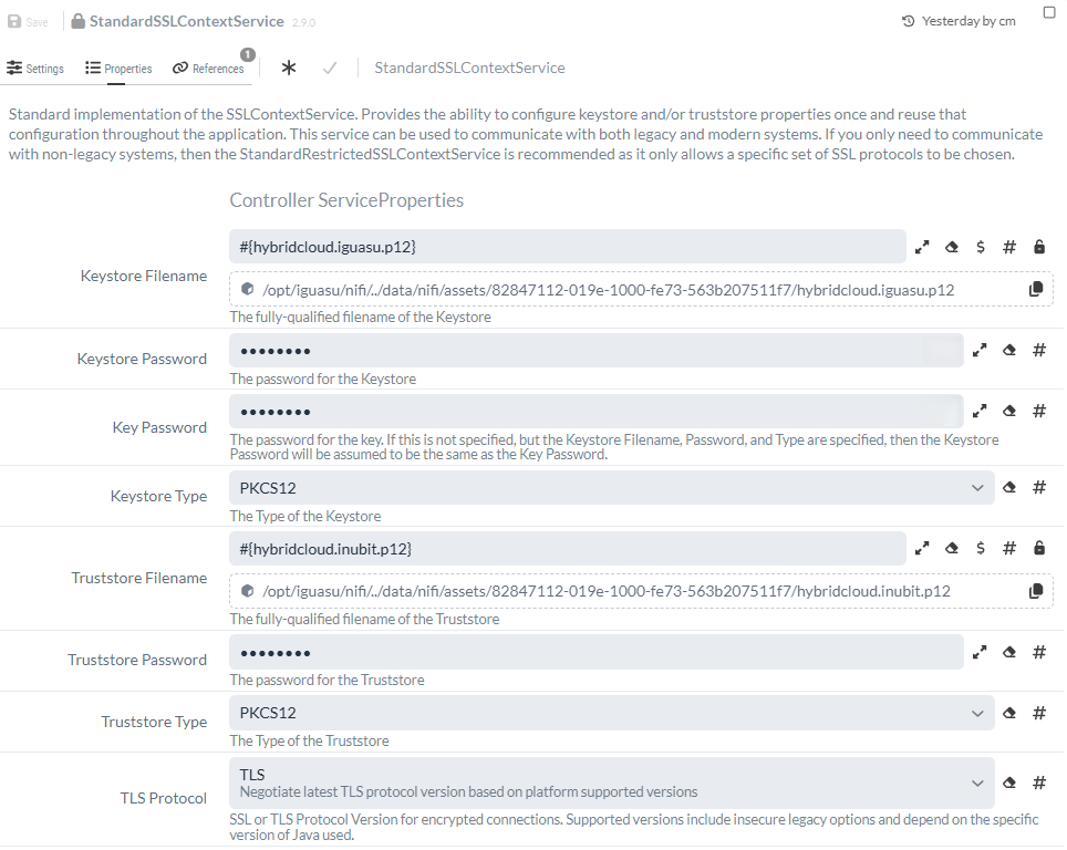
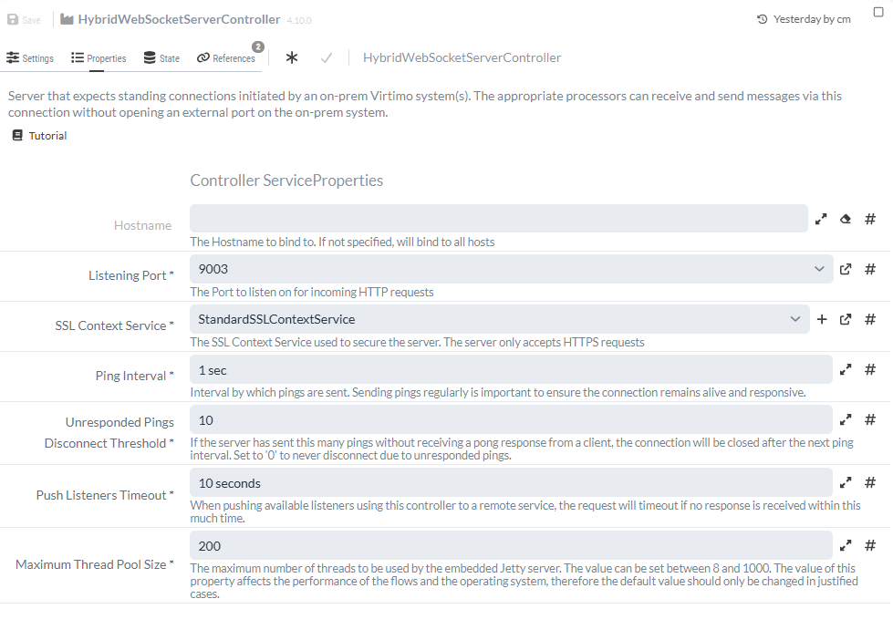
After creating the SSL Context Service, the HybridWebSocketServerController Service is also required to establish the WebSocket connection between the two systems. To configure this, you simply need to set the listening port and select an SSL Context Service. You can select the previously created Service from the dropdown menu as the SSL Context Service. The listening port, however, must be the port that was previously enabled by the administrator for communication between IGUASU and the INUBIT system. In this tutorial, the Port is 9003, but yours may be different.
With this information, the configured Service should look as follows:
|
It is only necessary to open a Port for IGUASU. This step is not required for the INUBIT system. |
Once both Services have been created, the necessary Processors required for communication with INUBIT can then be configured.
Part 4: Communication INUBIT → IGUASU
This section explains how messages can be sent from INUBIT to IGUASU in the cloud.
4.1 Receiving Data with the ListenInubit Processor
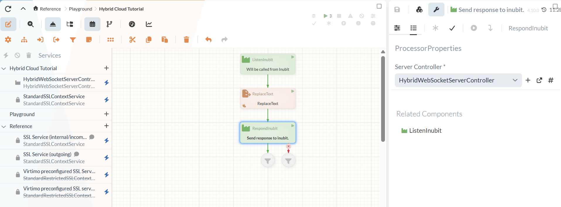
To enable communication between the two systems, the corresponding elements must first be created in IGUASU so that data can be received and responses sent. Data reception from an INUBIT system is handled by the ListenInubit Processor, which serves as the starting point of the flow in IGUASU.
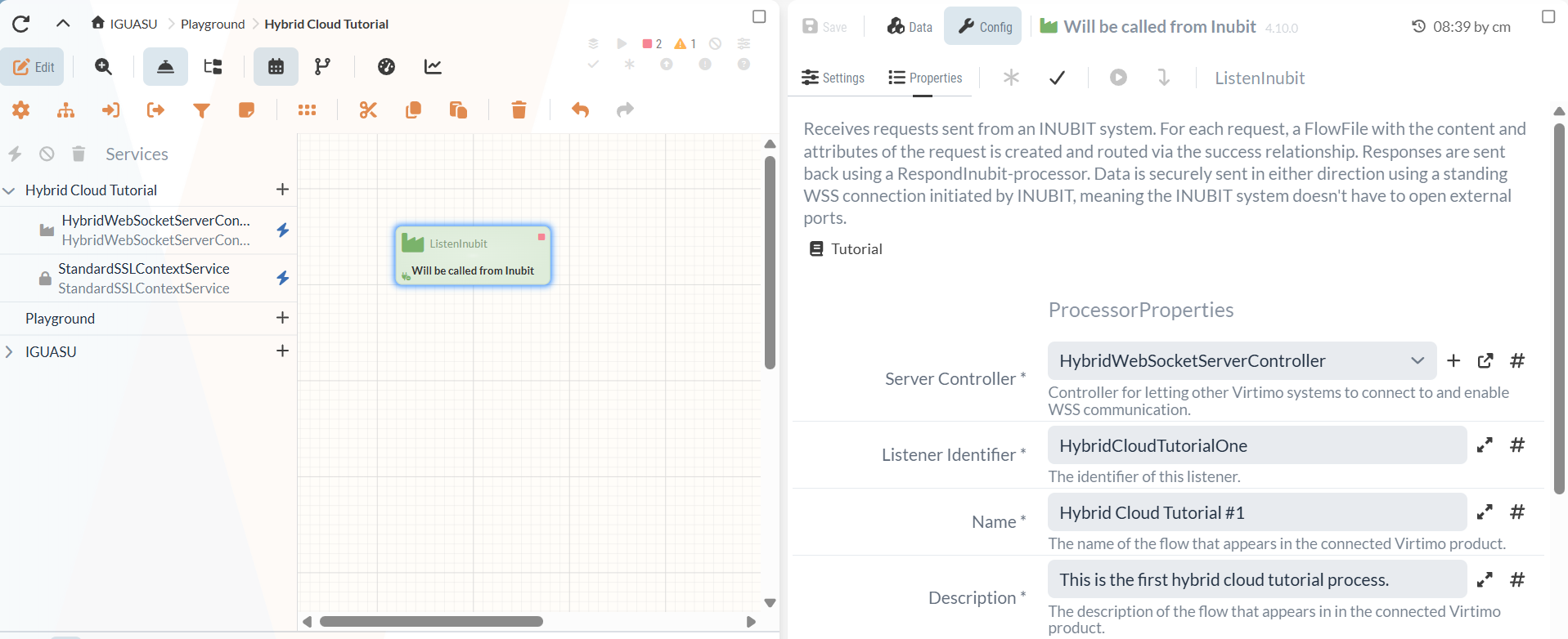
Four properties are available for configuring the Processor. The first setting to configure is the Listener Identifier, which can be used to distinguish and identify the listeners.
In addition, a server controller must be specified. For this setting, the previously created HybridWebsocketServerController Service is used, through which, among other things, the port configuration was performed.
Furthermore, a name must be specified for the Processor, which is also used to identify the flow. The entry defined here will be visible later in INUBIT during the configuration of the IGUASU connector, thereby enabling the correct entry point in the cloud to be found.
In addition, a description must be provided, which is also visible in INUBIT and thus further simplifies finding the correct listener in the other system.
Once the configuration is complete, the Processor should look as follows:
4.2 Data Processing and the RespondInubit Processor
Once the data can be received by the ListenInubit Processor in IGUASU, processing can begin. At this point, it would be possible to create a complex flow, easily integrate external Services, and set up various processing branches. However, to keep things simple within the scope of this tutorial and to focus on communication between the two systems, only a single, simple processing step will be performed.
For this purpose, the ReplaceText Processor is used to modify the FlowFile content.
The content is to be completely replaced, which is why the “ Replacement Strategy ” option “Always Replace” should be used.
Any text can be used as the “ Replacement Value,” since its sole purpose here is to indicate to INUBIT that the change was made by IGUASU.
In this example, The IGUASU Response at was entered along with the current time.
A possible configuration is shown in the following figure.

The RespondInubit Processor is used to resend the data to INUBIT at the end of processing or to generate a response in general. For configuration, only a server controller needs to be set for this Processor. Similar to the ListenInubit processor, the HybridWebsocketServerController service is used for this purpose.
This completes the flow in IGUASU for receiving and processing data from INUBIT. At this point, all new Services and Processors should be activated or set to “Start.”
4.3 Configuring the IGUASU Connectors in INUBIT
To send messages from a local INUBIT installation to IGUASU in the cloud, a workflow must first be created in INUBIT. To simplify communication between the two systems, INUBIT offers the IGUASU Connector for this purpose, which can be used to establish a connection via WebSockets.
To configure the IGUASU Connector in INUBIT, you will need:
-
The URL of the IGUASU endpoint (from Part 1) in the format: "<URL>/hybrid".
-
A download of the IGUASU-side certificate (from Part 2).
-
A download of the INUBIT-side keystore (from Part 2).
A comprehensive description of how to configure these elements can be found in the INUBIT documentation under the section “IGUASU Connectors.”
4.4 Start and Test the Workflow
Now that the configurations in INUBIT are complete, the workflow should be activated in INUBIT, a starting point set on the IGUASU connector, and finally started using “Start test without file.” Afterward, information should be received in IGUASU via the ListenInubit Processor, which will then be visible as a FlowFile.
After the content has been modified by the ReplaceText Processor, the data is then sent back to INUBIT, where it is displayed with the new text and the additional metadata that was added in IGUASU in the form of attributes.
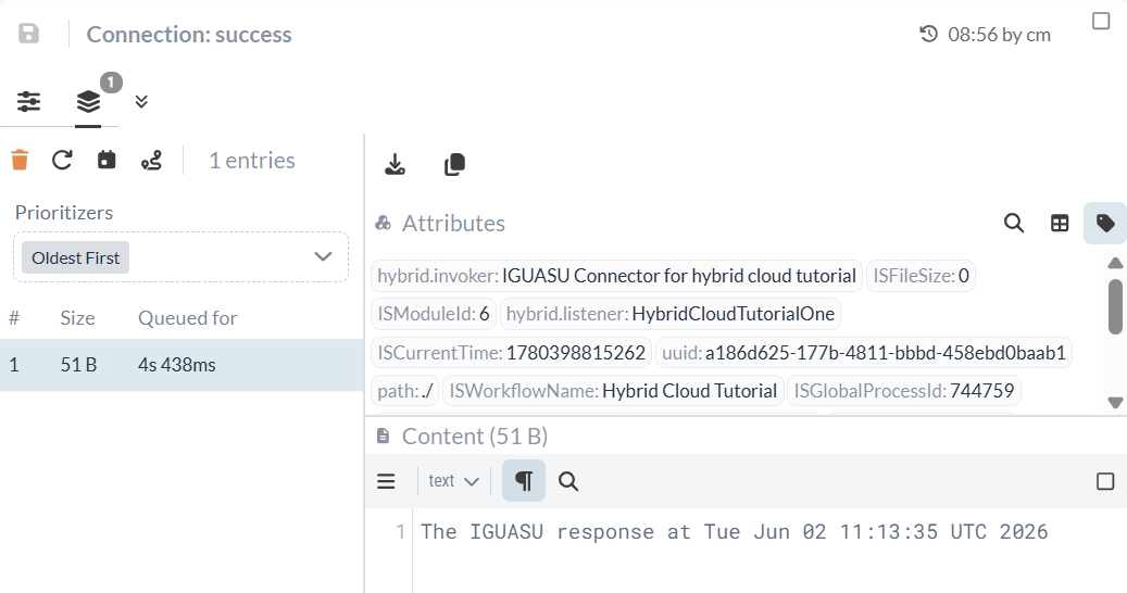
At the end of the flow created in IGUASU, the data in the FlowFile should look like the following figure:
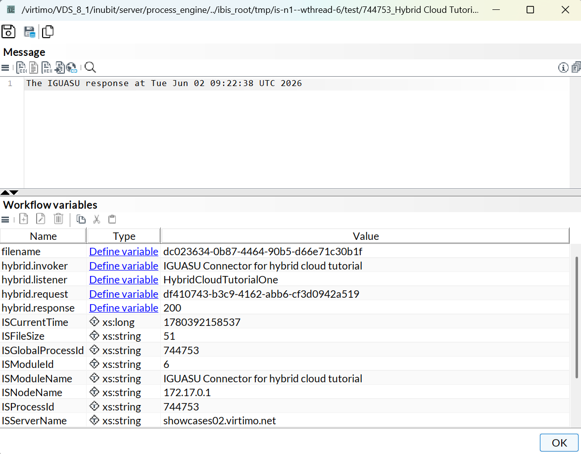
At the end of the workflow in INUBIT, the data in the watchpoint should look like the following figure:
Part 5: Communication from IGUASU to INUBIT
While Parts 1–4 of this tutorial focused on communication initiated by INUBIT, in which a response was sent back by IGUASU, it is also possible to initiate a workflow via IGUASU.
5.1 IGUASU Connector as a Listener
To map processes in which IGUASU calls an INUBIT workflow, the system also offers a custom Processor. However, to receive this data from IGUASU, you must first create an IGUASU connector in INUBIT to which the data generated in IGUASU can be sent. This is configured exactly as described in Section 4.3 of this tutorial, with the exception that the Connector Type must be set to Input Connector, since data is to be received from IGUASU. As before, you can find detailed information on the configuration in the section on IGUASU Connectors.
5.2 Transferring Data with the InvokeInubit Processor
Once the configuration in INUBIT is complete and a listener is available to which data can be transferred, the configuration in IGUASU can be carried out. The InvokeInubit Processor can be used to send requests from IGUASU to INUBIT. To demonstrate this in this tutorial, data must first be generated in IGUASU that can be transferred to the INUBIT system.
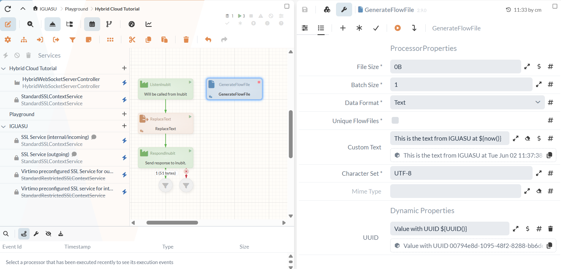
To create a simple FlowFile, you can use the GenerateFlowFile Processor, as in other tutorials. To fully demonstrate the data transfer, a unique content and an attribute for the corresponding FlowFile should be created here.
Therefore, first, the Custom Text option is configured, and the following text is entered here:
This is the text from IGUASU at ${now()}.
In addition, an attribute can be defined that is also transmitted to INUBIT as metadata and is subsequently available in the system as a variable.
For this purpose, a dynamic property can be used to create an attribute.
A suitable attribute, for example, is the unique ID of the FlowFile, so that Value with UUID: ${UUID()} can be entered.
The complete configuration of the GenerateFlowFile Processor then looks as follows:
Next, the InvokeINUBIT Processor is created, which can be used to transfer this generated data to INUBIT. To configure it, a server controller must first be defined again, using the previously created HybridWebSocketServerController.
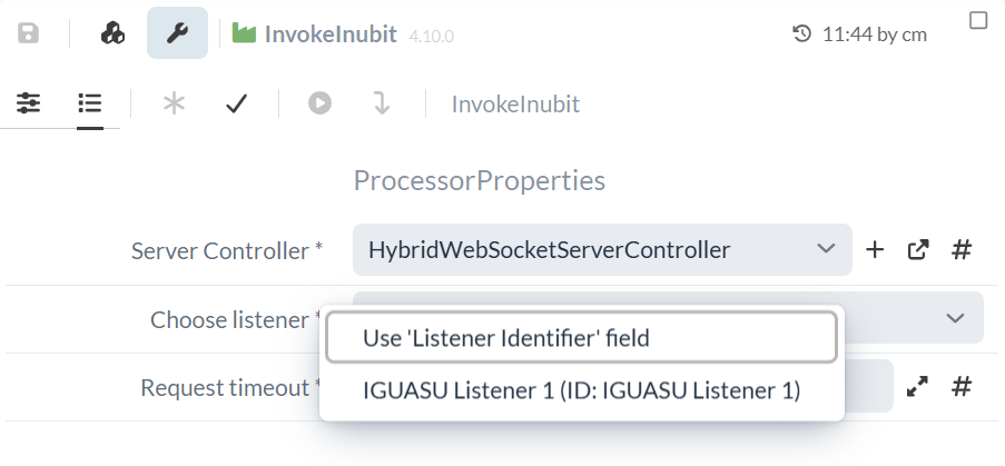
Next, the “Choose Listener” option must be configured, with two different options available:
First, you can use the “ Use 'Listener Identifier' field ” option to specify the ID of the listener in INUBIT to which the FlowFile should be transferred.
However, if a connection between the two systems already exists, all available listeners should be listed in the drop-down menu.
Here, for example, is the “IGUASU Listener 1,” which bears the name of the corresponding IGUASU connector in INUBIT.
|
If this listener selection is not available to you, we recommend first completing Part 4 of this tutorial, as it establishes a connection between the two systems. In addition, the workflow must be published and activated in INUBIT in order to see the listener selection once a connection is established. |
You can also optionally configure the “Target unavailable” setting, which allows you to define the behavior in the event of connection issues. The “Route to ‘unavailable’ relation” option is useful here, as it allows you to define a branch with additional processing steps. As part of this tutorial, a funnel will be inserted at this point to serve as the endpoint.
The final workflow will then look as follows:
When the GenerateFlowFile Processor is now executed using " Run Once," the defined data is generated and then sent to the listener created in INUBIT.
