Development and test
Flows
Created elements can be edited as required in Edit mode A chain of connections of elements in the diagram, i.e. a data flow, is referred to as a flow.
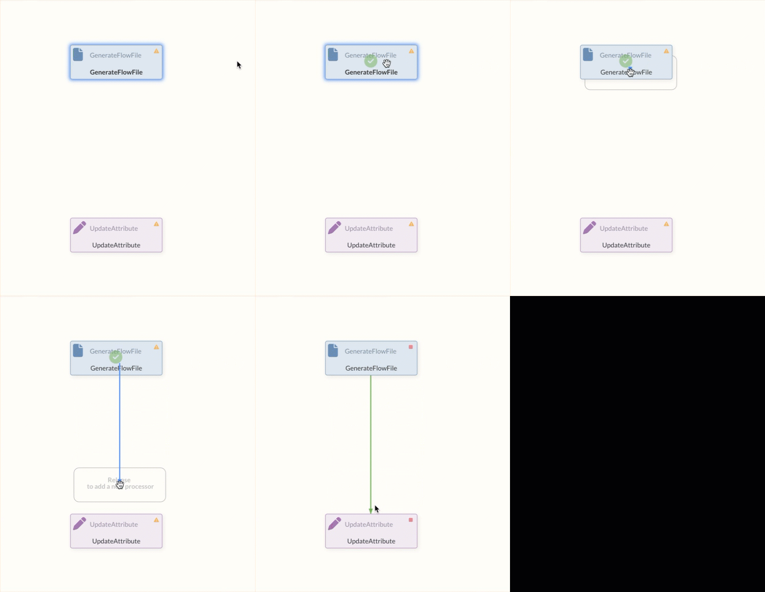
New elements can be created either by dragging and dropping from the toolbar or by releasing a line onto an empty space in the diagram.
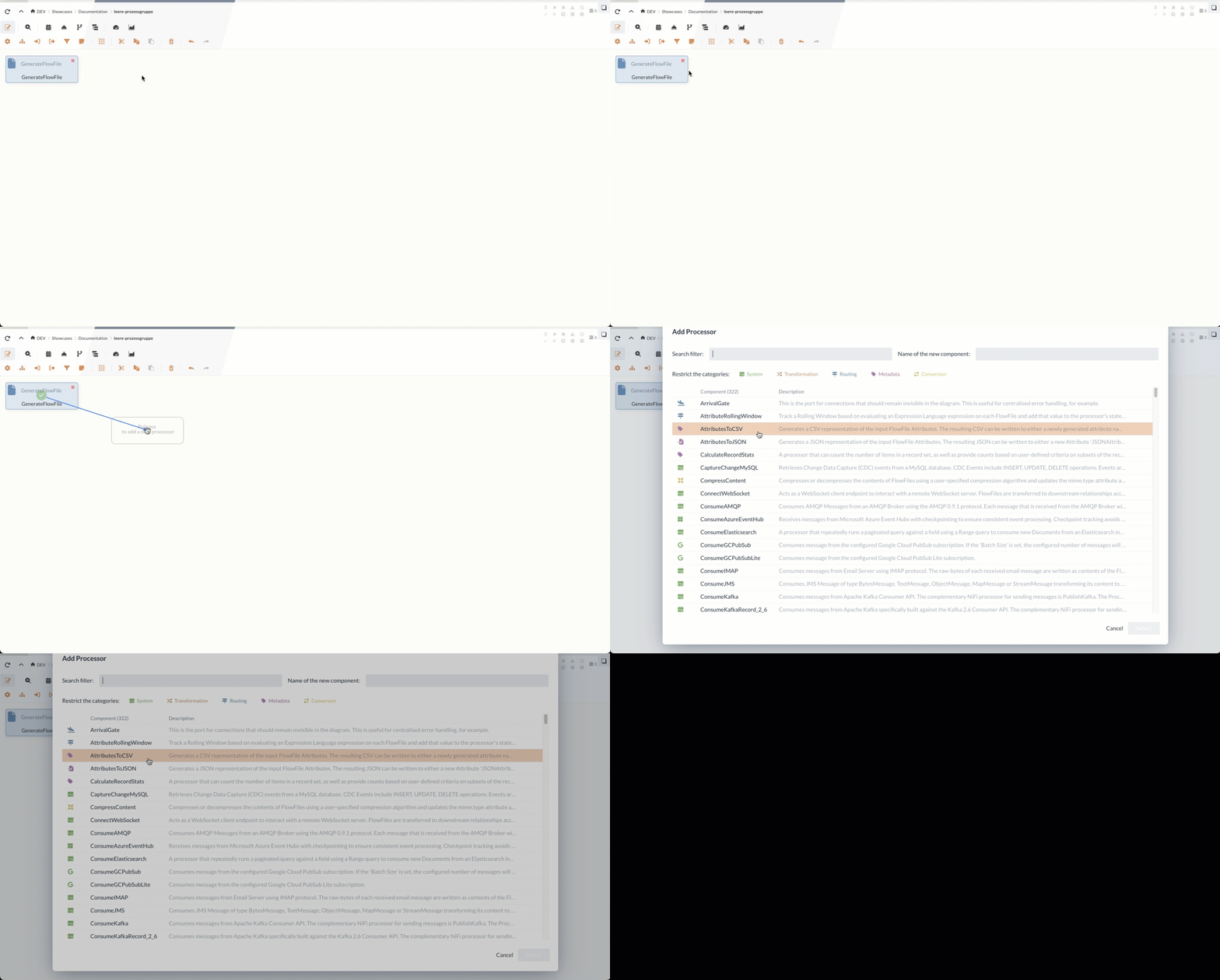
The elements can also create success and failure relationships directly. The darker circles on each element contain tooltips. These provide a more detailed description of the possible relationships.

To connect elements, draw the line to the target element from the slightly darker circle in the center.
Connection types
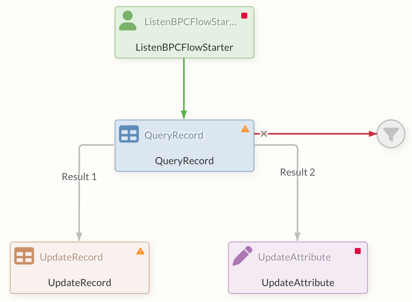
For most Processors, the "success" and "failure" connection options are available by default, which are executed depending on the success or failure of the process.
The gray arrow represents the default connection, which ultimately contains all connection types.
An additional window opens for the connection, in which the specific type of connection can be selected.
Furthermore, certain Processors have additional connection types that can be used for specific results or events.

In addition, some Processors have the option of using dynamic properties to create your own connection types.
To improve clarity, the displayed edges of the connections are color-coded or described in the case of dynamic properties or specific events.
When already connected elements are moved, the links are retained and dynamically adapt to the repositioning.
To create a simple flow, see 5-minute tutorial.
Changing the edges
The created connections can also be visually changed and bent in order to achieve a better overview in the data flow. If the edges are moved in edit mode, points appear on the edge that can be used for shaping.
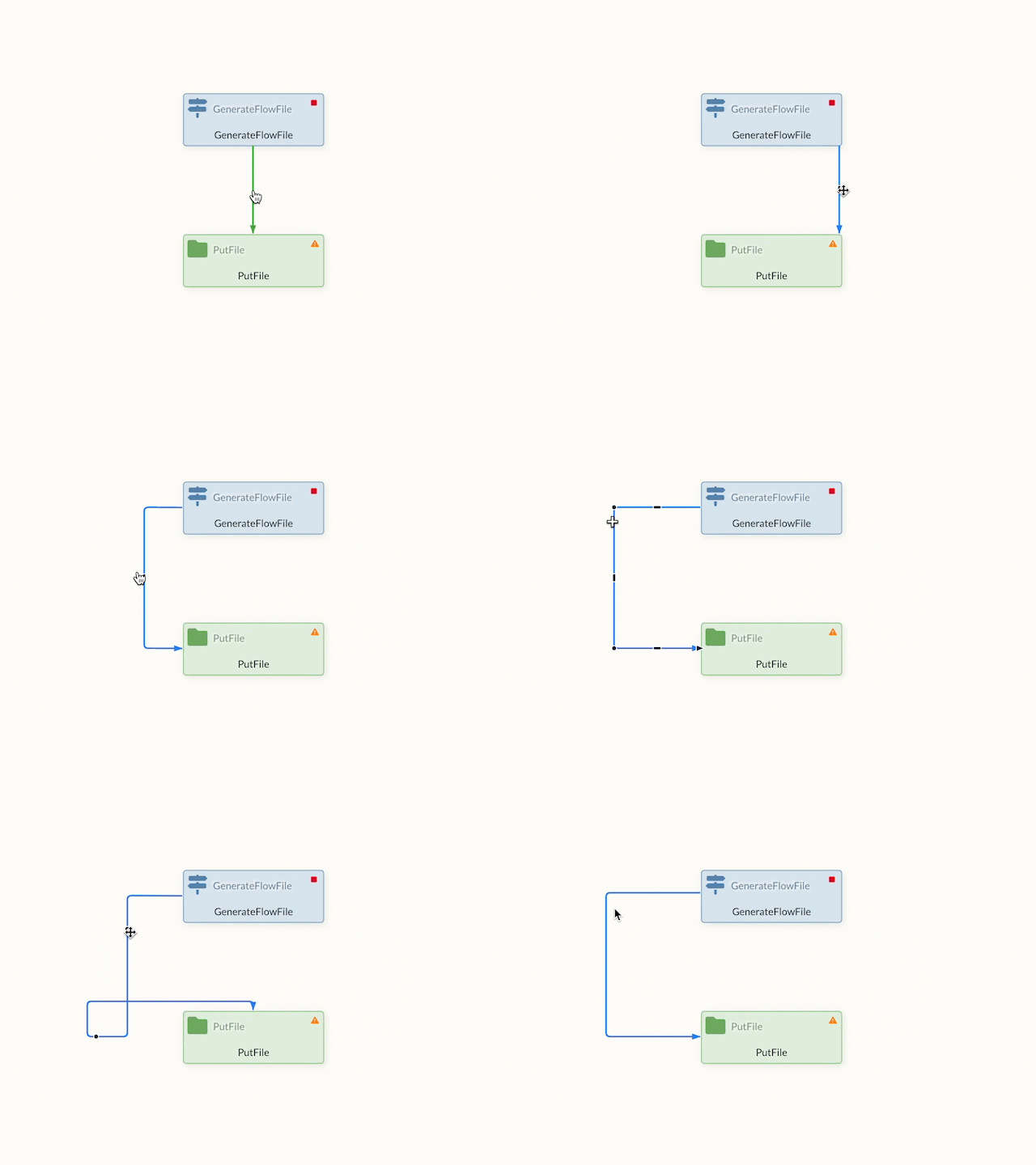
Changes that have been made can be reset via the context menu.
Execution of flows
Processors or flows can be executed in different ways, individually or in the entire Process Group.
The States of Processors can be adjusted via the context menu (by right-clicking on the element) and thus started or stopped.
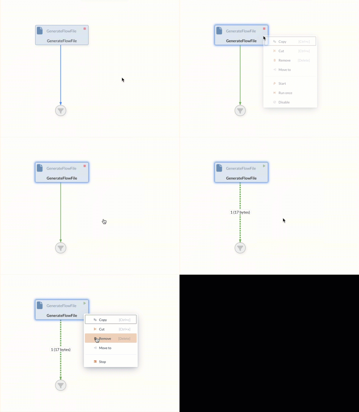
If, on the other hand, the context menu is called up on an empty area and the status is changed, this action applies to all Processors in the current and all subordinate Process Groups.
The configuration of the execution, such as the frequency of execution, takes place at Configuration area.
While Processors are in the RUNNING state, this configuration is taken into account.
This state is activated by selecting the Start command.
If, on the other hand, the context menu Run Once is used to execute the Processor, the Processor is only executed once.
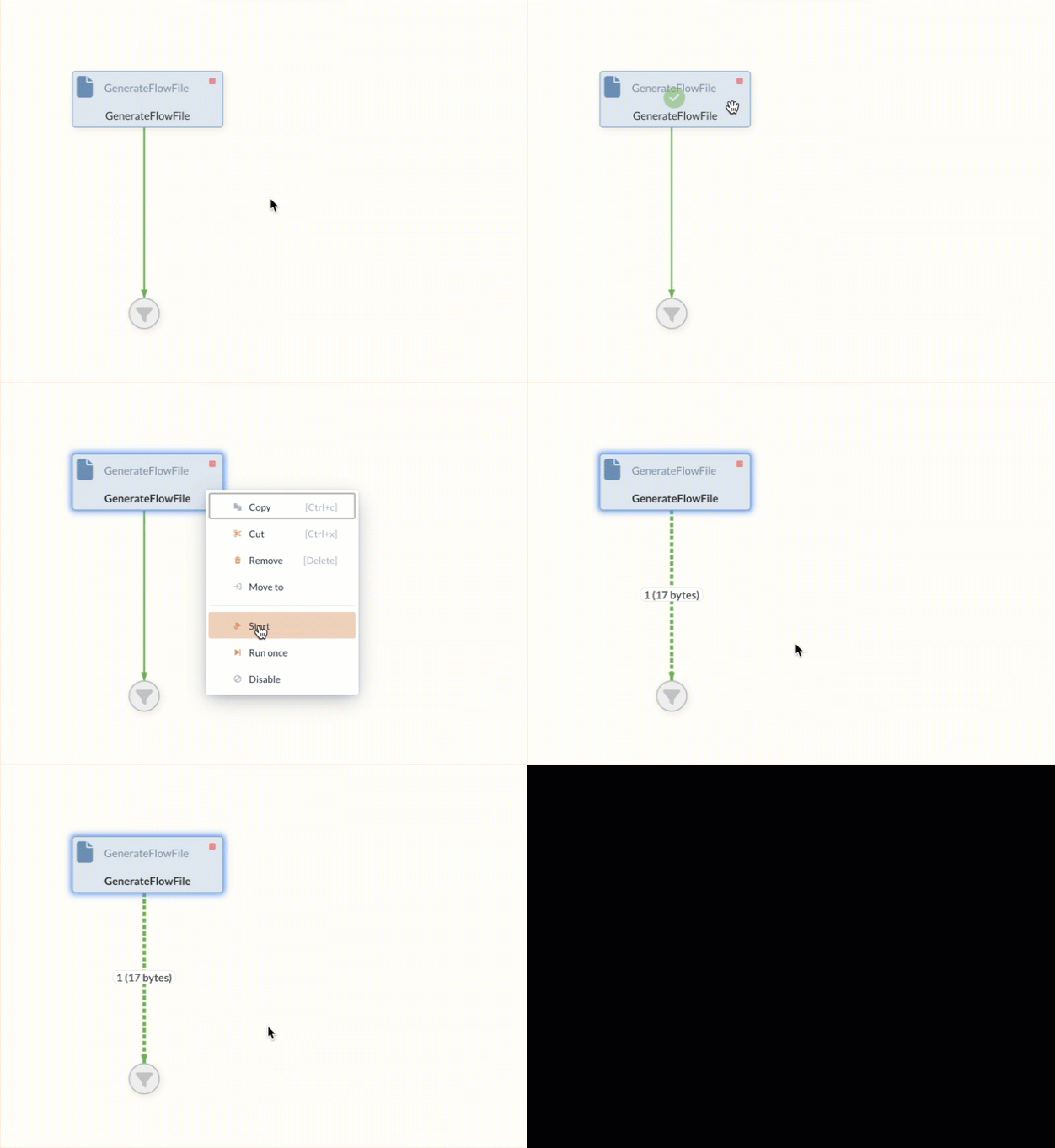
All previous executions can be stored in an Event table
Success Relation
The Success Relation is a connection that is available to all Processors. FlowFiles are always forwarded to the Success Relation if processing in the Processor was successful.
The Success Relation can be recognized in the Diagram by the green color, which is not used by any other relation.

Failure Relation
The Failure Relation, which is available to most Processors as an option, is often the first step for appropriate error handling.
FlowFiles are always forwarded to this relation if an error has occurred during processing within the Processor.
This means that errors that occur can be easily intercepted in order to react appropriately to them in a designated branch by connecting further Processors.
The Failure Relation can be recognized in the Diagram by the red color, which is not used by any other relation.
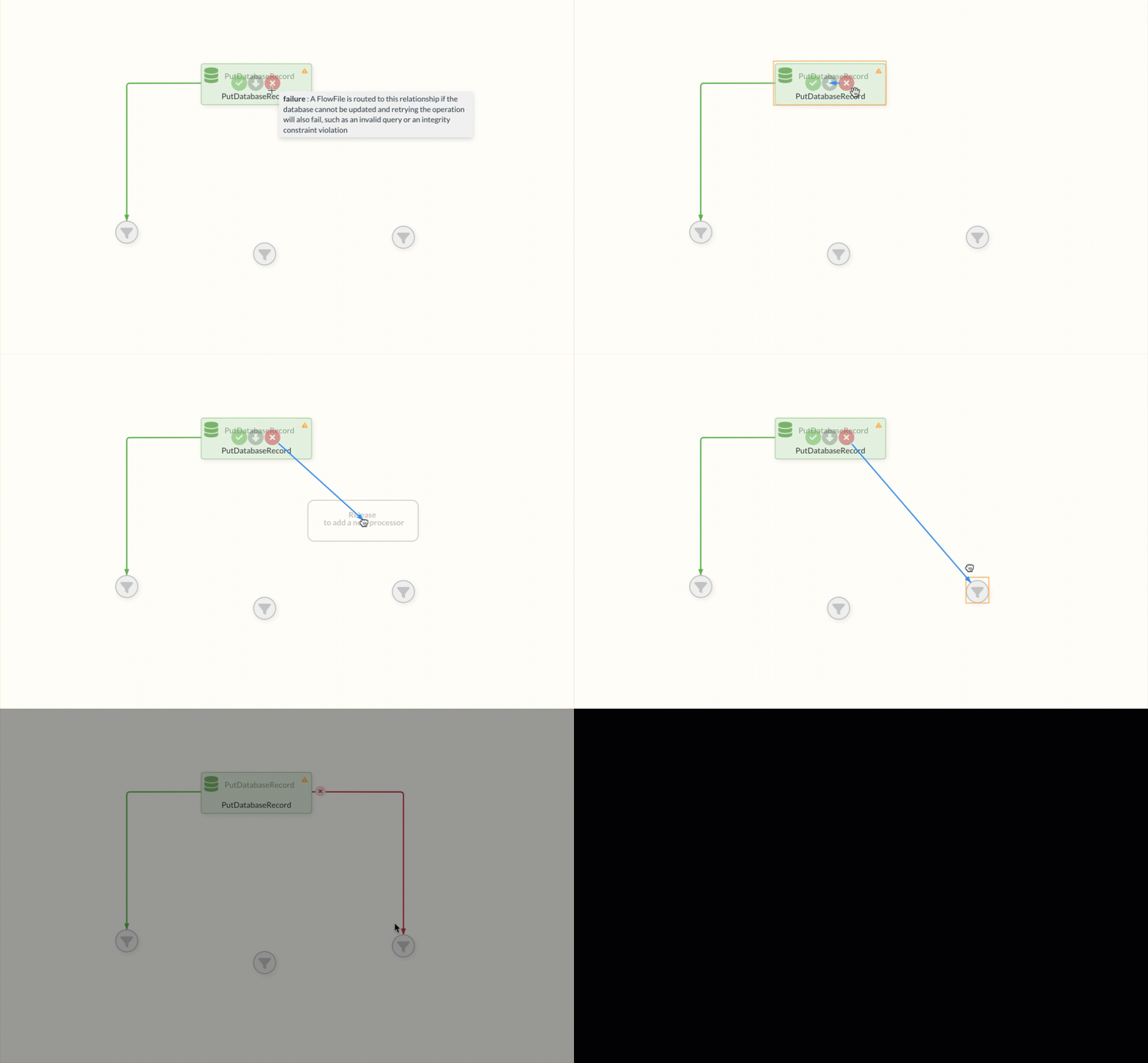
The first endpoints are often Funnels to indicate that further processing steps should be added at the corresponding point. This also helps users to detect errors by making the FlowFiles visible on the failure edge.
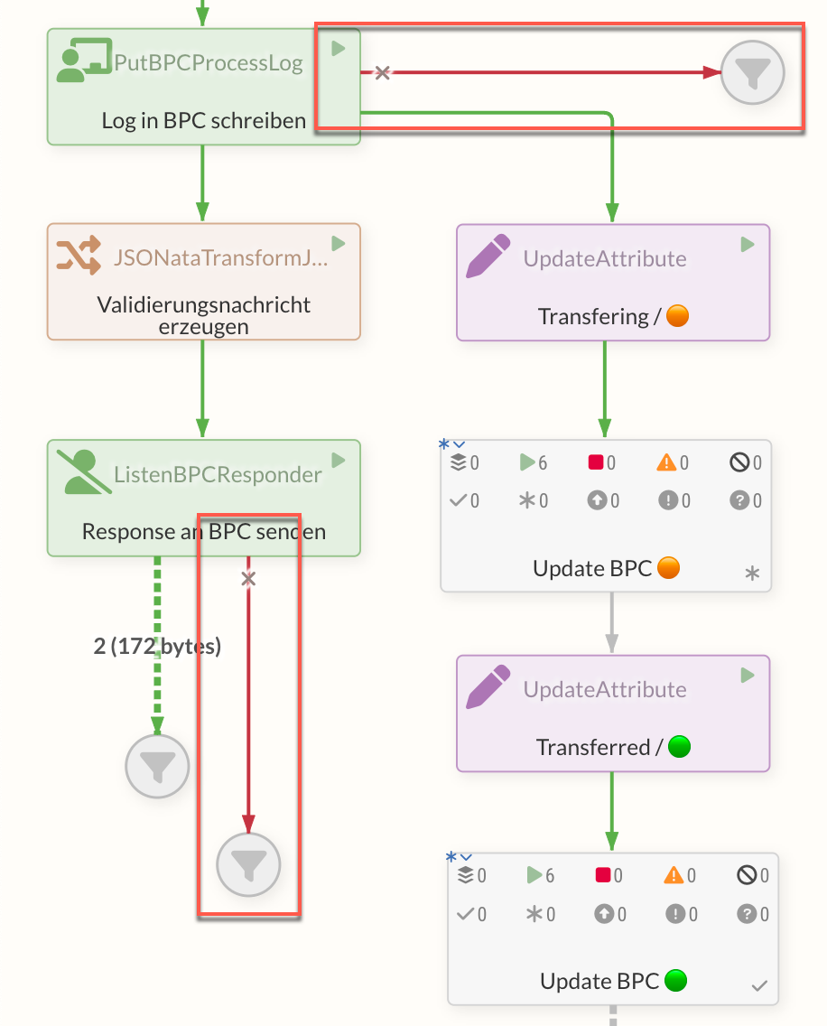
FlowFiles can be analyzed at this point to identify the cause of the error. For this purpose, the Event table provides further information on the Processor’s faulty event.
For appropriate error handling, however, it is important not only to collect the FlowFiles of an error in a Funnels, but also to process them in further steps in order to address existing errors appropriately.
It is also possible to analyze generated errors with the Metro Processors and to bundle the error handling.
Further relations
For different Processor types, there are other relation types in addition to the Failure or Success relations.
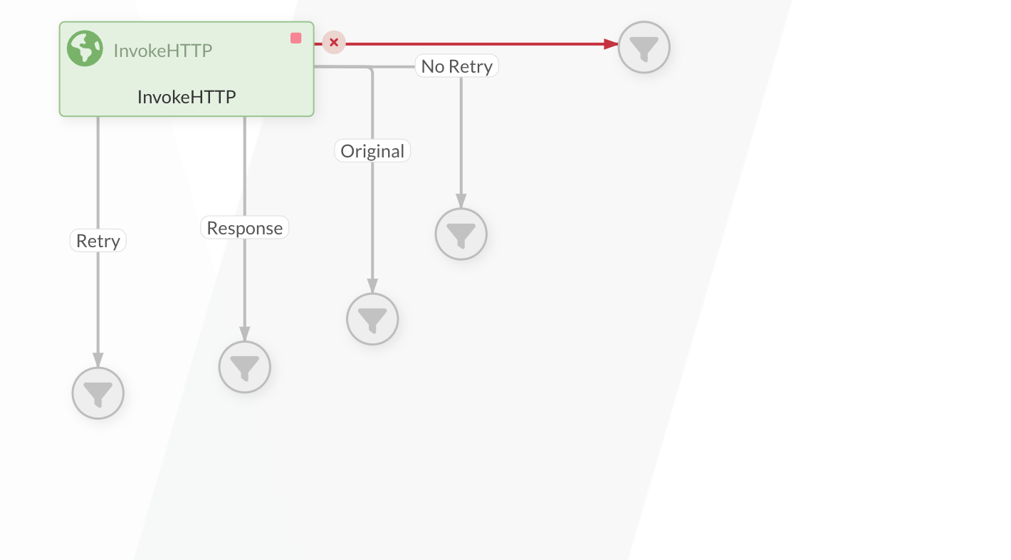
There are four further relations that can be used with the InvokeHttp Processor. These include Retry, Response, Original and No Retry.
-
Retry
If the response code is between 500 and 599, it is forwarded here. -
Response
If the Processor sends out a request and the response is successful, the original request (FlowFile) is forwarded via this relation. -
Original
If a request is sent to the Processor and it is successful, the original request (FlowFile) is forwarded via this relation. -
No Retry
If the response code is between 400 and 499, it is forwarded here.
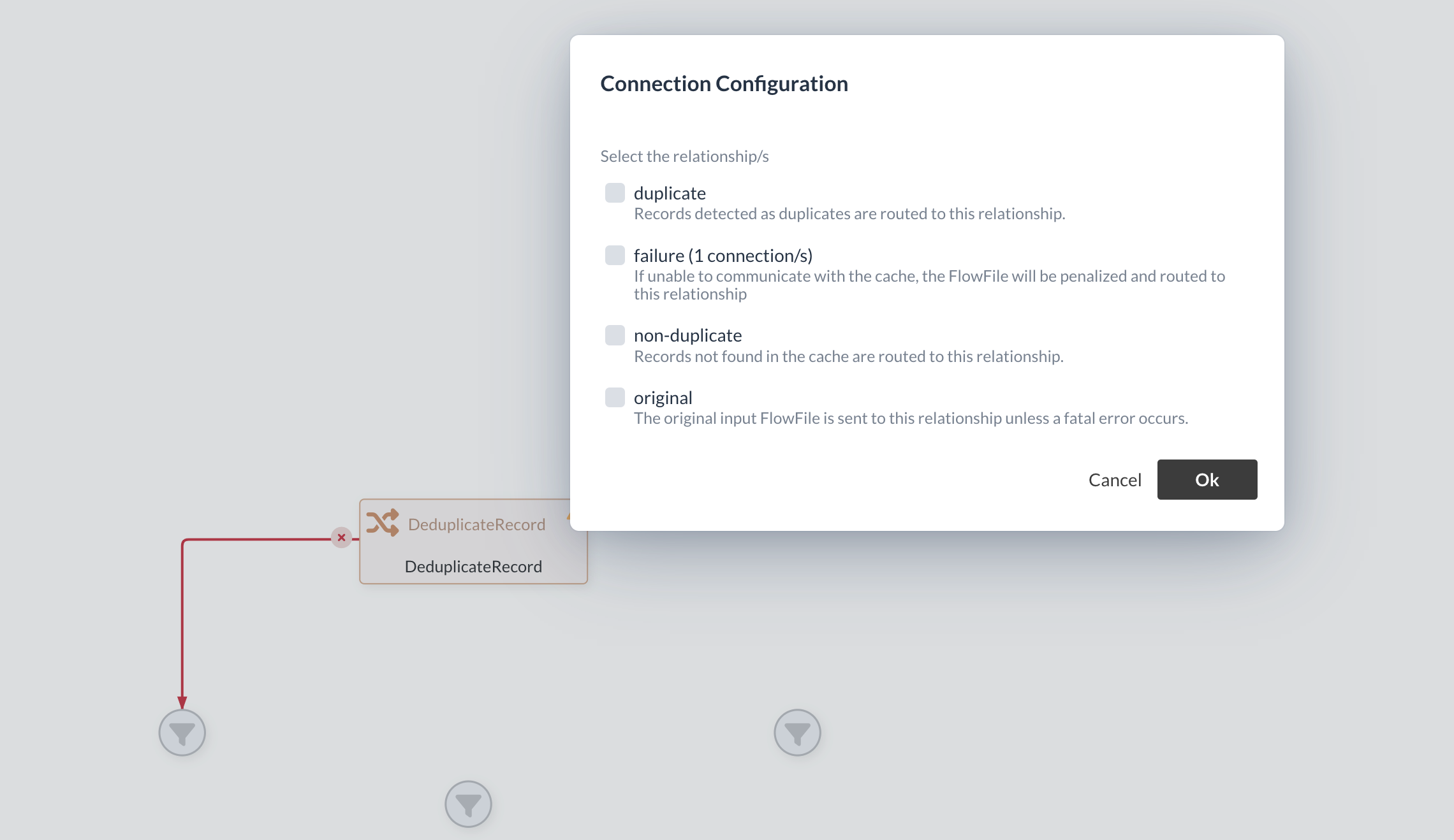
In the case of the Duplicate Processor, there are three further relations that belong specifically to this Processor and replace the Success relation.
FlowFiles
Data packets that are transmitted via the resulting edges are referred to as FlowFiles. FlowFiles are displayed on the created edge itself in the Diagram and can also be viewed by clicking on the edge in the Processor’s queue.
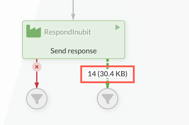
FlowFiles have content and metadata, which are referred to as attributes in IGUASU. Both the content and the attributes can be used for routing or for transmitting information to other Processors or external systems.
Testing individual Processors
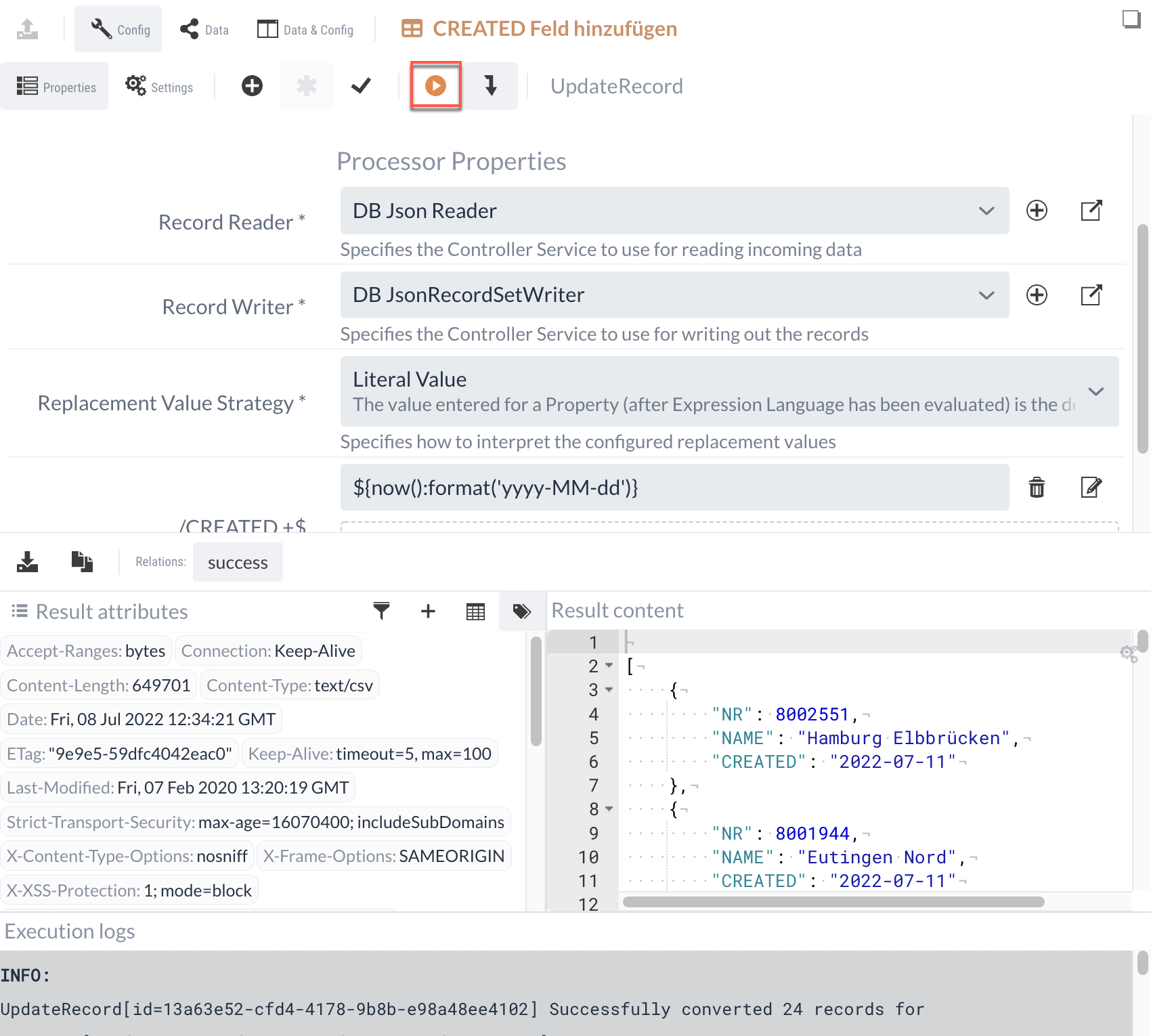
As previously mentioned, a Processor can be tested in the Config Panel using the button in the toolbar. For the tests, the data from the Data Panel which can be loaded manually or by selecting an event from the Event table were stored.
|
It should be noted that there is an actual execution in IGUASU with the set data. |
The execution opens a result panel in the lower area.
The buttons are used to display which Processor outputs would have taken the data.
Depending on the selection of these buttons, the associated data of the execution is displayed.
If there were logs or console outputs during the execution, these are also displayed.
The execution can be repeated as often as required. Changed data of the properties, but also the input data and attributes from the execution view are taken into account.
In the screenshot, the execution data and the configuration of the Processor are displayed one below the other. The previously mentioned simultaneous display of the Config Panel and Data Panel can be used in isolated execution to also display and even adjust the input data to which the execution of the Processor refers.
